AT85C51SND3Bx
Receiver
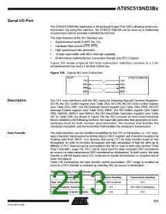
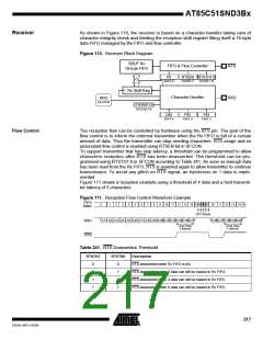
As shown in Figure 110, the receiver is based on a character handler taking care of
character integrity check and feeding the reception shift register filling itself a 16-byte
data FIFO managed by the FIFO and flow controller.
Figure 110. Receiver Block Diagram
SBUF Rx
16-byte FIFO
FIFO & Flow Controller
RTS
RXD
RI
SINT.0
RTSEN RTSTH1:0
SCON.2
SCON.1:0
Rx Shift Reg
Character Handler
BRG
CLOCK
OVERSF3:0
SFCON.7:4
OEI
SINT.4
PEI
SINT.3
FEI
SINT.2
Flow Control
The reception flow can be controlled by hardware using the RTS pin. The goal of the
flow control is to inform the external transmitter when the Rx FIFO is full of a certain
amount of data. Thus the transmitter can stop sending characters. RTS usage and so
associated flow control is enabled using RTSEN bit in SFCON.
To support transmitter that has stop latency, a threshold can be programmed to allow
characters reception after RTS has been deasserted. The threshold can be pro-
grammed using RTSTH1:0 in SFCON according to Table 241. As soon as enough data
has been read from the Rx FIFO, RTS is asserted again to allow transmitter to continue
transmission. To avoid any glitch on RTS signal, an hysteresis on 1 data is imple-
mented.
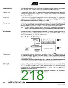
Figure 111 shows a reception example using a threshold of 4 data and a host transmit-
ter latency of 3 characters.
Figure 111. Reception Flow Control Waveform Example
FIFO
0
1
2
3
4
5
6
7
8
9
10 11 12 13 14 1514 1312 11 10
11 12 13 14 15
Index
RXD
RTS
CPU Read
C1 C2 C3 C4 C5 C6 C7 C8 C9 C10 C11 C12 C13 C14 C15
C16 C17 C18 C19 C20
Host Stop
Latency
Host Stop
Latency
Table 241. RTS Deassertion Threshold
RTSTH1
RTSTH0
Description
0
0
1
1
0
1
0
1
RTS deasserted when Rx FIFO is full.
RTS deasserted when 2 data can still be loaded in Rx FIFO.
RTS deasserted when 4 data can still be loaded in Rx FIFO.
RTS deasserted when 8 data can still be loaded in Rx FIFO.
217
7632A–MP3–03/06

 ATMEL [ ATMEL ]