AT85C51SND3Bx
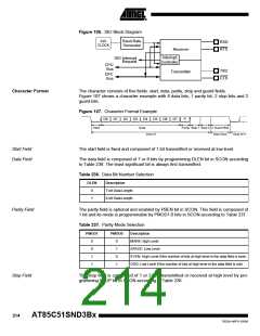
Table 238. Stop Bit Number Selection
STOP
Description
1 Stop Bit.
0
1
2 Stop Bits.
Guard Field
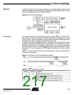
The guard field is not part of a character and is an optional inter-character spacing com-
posed of 0 to 3 bits transmitted at high level by programming GBIT1:0 bits in SCON
according to Table 239. The guard field allows transmitter to be compliant with con-
nected host (overrun avoiding) and is emitted after the last stop bit of a character.
Table 239. Guard Field Size Selection
GBIT1
GBIT0
Description
0
0
1
1
0
1
0
1
0 guard bit inserted (default).
1 guard bit inserted.
2 guard bits inserted.
3 guard bits inserted.
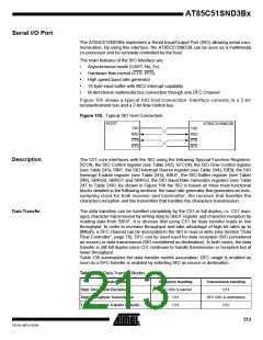
Baud Rate Generator
The Baud Rate Generator is fed by the SIO clock as detailed in Section “SIO Clock Gen-
erator”, page 32. The maximum baud rate can be achieved by selecting the high
frequency issued by a division of the PLL clock. The clock generated is an oversampling
clock. The oversampling factor is programmable using OVRSF3:0 bits in SFCON with
oversampling factor equal to OVRSF3:0 + 1 (e.g.: OVRSF3:0= 11 for a 12x
oversampling).
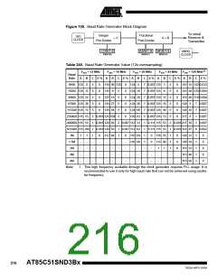
Baud Rate Calculation
As shown in Figure 109, the baud rate generator is composed of an integer divider fol-
lowed by a fractional divider. The baud rate formula is given by Figure 108. In this
formula, variables must be chosen as followed:
–
OVRSF
The oversampling factor depends mainly on the frequency and the quality of
the medium transporting the data. In any case, OVSF3:0 must not be less
than 4 for proper majority vote in bit reception.
–
–
ADIV
Must be greater than BDIV and less than (K ⋅ OVRSF). K being the number
of bit in a character (from 9 to 11).
BDIV
Must be greater than 1/ε according to the tolerance on the real baud rate
BRR compare to the theoretical baud rate BRT.
ε being the error: ε= K ⋅ |1/BBT - 1/BRR|.
Table 240 shows some programming values depending on the SIO frequency and con-
sidering an oversampling factor of 12 (OVERSF3:0= 11).
Figure 108. Baud Rate Formula
FSIO ⋅ BDIV
ADIV ⋅ CDIV ⋅ OVRSF
Baud_Rate=
215
7632A–MP3–03/06

 ATMEL [ ATMEL ]