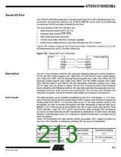
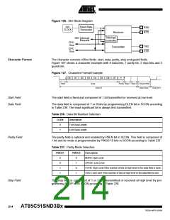
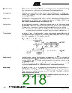
Figure 106. SIO Block Diagram
Baud Rate
Generator
SIO
CLOCK
RXD
RTS
Receiver
Interrupt
Controller
SIO Interrupt
Request
CPU
Bus
DFC
Bus
TXD
CTS
Transmitter
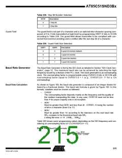
Character Format
The character consists of five fields: start, data, parity, stop and guard fields.
Figure 107 shows a character example with 8 data bits, 1 parity bit, 2 stop bits and 2
guard bits.
Figure 107. Character Format Example
D0
D1
D2
D3
D4
D5
D6
D7
P
Start
Data
Parity Stop 1 Stop 2 2 Guard Bits
Inter-Char
Char N
Char N+1
Start Field
Data Field
The start field is fixed and composed of 1 bit transmitted or received at low level.
The data field is composed of 7 or 8 bits by programming DLEN bit in SCON according
to Table 236. The least significant bit is always first transmitted.
Table 236. Data Bit Number Selection
DLEN
Description
0
1
7-bit Data Length.
8-bit Data Length.
Parity Field
The parity field is optional and enabled by PBEN bit in SCON. This field is composed of
1 bit and its mode is programmable by PMOD1:0 bits in SCON according to Table 237.
Table 237. Parity Mode Selection
PMOD1
PMOD0
Description
0
0
1
1
0
1
0
1
MARK: high Level
SPACE: Low Level
EVEN: High Level if the number of bits at high level in the data field is even.
ODD: Low Level if the number of bits at high level in the data field is odd.
Stop Field
The stop field is composed of 1 or 2 bits transmitted or received at high level by pro-
gramming STOP bit in SCON according to Table 238.
214
AT85C51SND3Bx
7632A–MP3–03/06

 ATMEL [ ATMEL ]