AT85C51SND3Bx
Serial I/O Port
The AT85C51SND3Bx implement a Serial Input/Output Port (SIO) allowing serial com-
munication. By using this interface, the AT85C51SND3B can be seen as a multimedia
co-processor and be remotely controlled by the host.
The main features of the SIO Interface are:
•
•
•
•
•
Asynchronous mode (UART: Rx, Tx)
Hardware flow control (CTS, RTS)
High speed baud rate generator
16-byte input buffer with MCU interrupt capability
Bi-directional multimedia bus connection through one DFC Channel
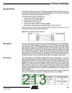
Figure 105 shows a typical SIO host connection. Interface consists in a 2-bit
receive/transmit bus and a 2-bit flow control bus.
Figure 105. Typical SIO Host Connection
HOST
AT85C51SND3B
TXD
RXD
CTS
RTS
TXD
RXD
CTS
RTS
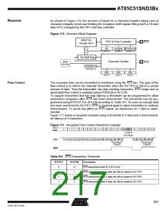
Description
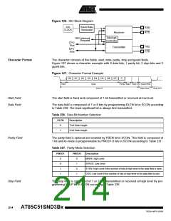
The C51 core interfaces with the SIO using the following Special Function Registers:
SCON, the SIO Control register (see Table 242); SFCON, the SIO Flow Control register
(see Table 243); SINT, the SIO Interrupt Source register (see Table 244); SIEN, the SIO
Interrupt Enable register (see Table 245); SBUF, the SIO Buffer register (see Table
246); SBRG0, SBRG1 and SBRG2, the SIO Baud Rate Generator registers (see Table
247 to Table 249). As shown in Figure 106 the SIO is based on three main functional
blocks detailed in the following sections: the baud rate generator that generates an over-
sampling clock for both receiver and transmitter, the receiver that handles the
characters reception and the transmitter that handles the characters transmission.
Data Transfer
The data transfers can be handled completely by the C51 in full duplex, i.e. C51 man-
ages character transmission by writing data to SBUF register and character reception by
reading data from SBUF. It is obvious that using C51 for data transfer leads to low
throughput. In order to increase throughput and take advantage of high bit rates up to
8Mbit/s, a DFC channel can be associated to the SIO in read or write (see Section “Data
Flow Controller”, page 78). DFC can be used used for data reception (SIO considered
as source) or data transmission (SIO considered as destination). In both cases, the data
transfer is still full duplex since C51 continues to handle transmission or reception but at
lower throughput.
Table 235 summarizes the data transfer modes association. DFC usage is enabled as
soon as a DFC transfer is enabled by selecting SIO as source or destination.
Table 235. Data Transfer Modes
Transfer Modes
High Throughput Reception
High Throughput Transmission
Low Throughput Transfer (default)
Reception Handling
Transmission Handling
DFC (SIO is source)
C51
DFC (SIO is destination)
C51
C51
C51
213
7632A–MP3–03/06

 ATMEL [ ATMEL ]