AT85C51SND3Bx
Bit
Bit
Number
Mnemonic Description
Data Transfer Enable Bit
Set to enable data transmission or reception immediately or after response has
been received.
2
DATEN
Cleared by hardware after the CRC reception in reception mode or after the busy
status if any in transmission mode.
Response Command Enable Bit
1
0
RXCEN
TXCEN
Set to enable the reception of a response following a command transmission.
Cleared by hardware when response is received.
Command Transmission Enable Bit
Set to enable transmission of the command FIFO to the card.
Cleared by hardware when command is transmitted.
Reset Value = 0000 0000b
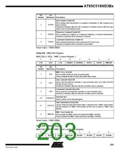
Table 223. MMCON2 Register
MMCON2 (1.B3h) – MMC Control Register 2
7
6
5
4
3
2
1
0
FCK
DCR
CCR
DBSIZE1
DBSIZE0
DATD1
DATD0
MMCEN
Bit
Bit
Number
Mnemonic Description
MMC Force Clock Bit
7
6
FCK
DCR
Set to enable the MCLK clock out permanently.
Clear to disable the MCLK clock and enable flow control.
Data Controller Reset Bit
Set to reset the data line controller in case of transfer abort, or to reset CRC16S
bit after an error occurs.
Cleared by hardware after the data line controller reset is achieved.
Command Controller Reset Bit
5
CCR
Set to reset the command line controller in case of transfer abort.
Cleared by hardware after the data line controller reset is achieved.
Data Bus Size
4-3
DBSIZE1:0
Refer to Table 219 for bits description.
Data Transmission Delay Bits
Used to delay the data transmission after a response from 3 MMC clock periods
(all bits cleared) to 9 MMC clock periods (all bits set) by step of 2 MMC clock
periods.
2-1
0
DATD1:0
MMCEN
MMC Clock Enable Bit
Set to enable the MMC clocks and activate the MMC controller.
Clear to disable the MMC clocks and freeze the MMC controller.
Reset Value = 0000 0000b
Table 224. MMBLP Register
MMCON2 (1.B4h) – MMC Block Length LSB Register
7
6
5
4
3
2
1
0
BLEN7
BLEN6
BLEN5
BLEN4
BLEN3
BLEN2
BLEN1
BLEN0
203
7632A–MP3–03/06

 ATMEL [ ATMEL ]