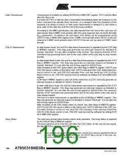
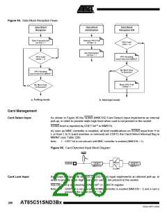
Figure 94. Data Block Reception Flows
Data Block
Reception
Data Block
Initialization
Data Block
Reception ISR
Start Transmission
Unmask FIFO Full
FIFO Full?
HFRI = 1?
DATEN = 1
HFRM = 0
Start Reception
DATEN = 1
FIFO Reading
read 8 data from MMDAT
FIFO Full?
HFRS = 1?
No More Data
To Receive?
FIFO Reading
read 8 data from MMDAT
Mask FIFO Full
HFRM = 1
No More Data
To Receive?
a. Polling mode
b. Interrupt mode
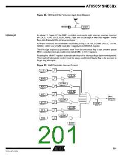
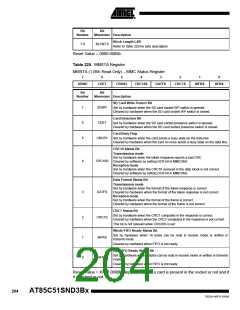
Card Management
Card Detect Input
As shown in Figure 95 the SDINS (MMC/SD Card Detect) input implements an internal
pull-up, in order to provide static high level when card is not present in the socket.
SDINS level is reported by CDET bit(1) in MMSTA.
As soon as MMC controller is enabled, all level modifications on SDINS input from H to
L or from L to H (card insertion or removal) set CDETI, the Card Detect Interrupt flag in
MMINT (see Table 226).
Note:
1. CDET bit is not relevant until MMC controller is enabled (MMCEN = 1).
Figure 95. Card Detection Input Block Diagram
IOVDD
RPU
SDINS
CDET
MMSTA.6
CDETI
MMINT.7
Card Lock Input
As shown in Figure 96 the SDLCK (SD Lock) input implements an internal pull-up, in
order to provide static high level when card is not present in the socket.
SDLCK level is reported by SDWP bit(1) in MMSTA register.
Note:
1. SDWP bit is not relevant until MMC controller is enabled (MMCEN = 1) and a card is
present in the socket (CDET = 0).
200
AT85C51SND3Bx
7632A–MP3–03/06

 ATMEL [ ATMEL ]