TSC695F
Package Description
Thermal Characteristics The thermal performance of a package is measured by its ability to dissipate the power
required by the device into its surroundings. The electrical power drawn by the device
generates heat on the top surface of the die. This heat is conducted through the pack-
age to the surface and then transferred when there is surrounding air by convection.
Each heat transfer step has corresponding resistance, when there is surrounding air, to
the heat flow, which is given the value Rθ, the thermal resistance coefficient. Subscripts
are added to the coefficient to specify the two points that the heat is transferred
between. Commonly used coefficients are Rθja (junction to ambient air), Rθjc (junction
to case) and Rθca (case to ambient).
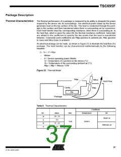
An electrical analogy can be made, as shown in Figure 23, to illustrate the heat flow of a
package. The heat transfer can be characterized mathematically by the following
equation:
Tj – Ta = P × Rθja
–
–
Where:
P = Device operating power (Watts)
Tj = Temperature of a junction on the device (°C)
Ta = Temperature of the surrounding ambient air (°C)
Rθja = Rθjc + Rθca in °C/W
Figure 23. Thermal Model
Rθja
Rθca
Heat Flow
Cavity
Rθjc
Die
Package
Table 8. Thermal Characteristics
Conditions
Rθ -
ja
Value
20 ~ 23
0.4
Unit
Temperature
Air
Blown air
jc
°C/W
25/90°C
ja
31 ~ 41
0.4
Stationary air
jc
37
4118H–AERO–06/03

 ATMEL [ ATMEL ]