AX88179
USB 3.0 to 10/100/1000M Gigabit Ethernet Controller
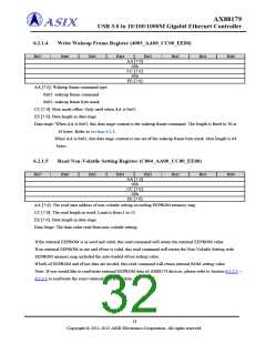
6.2.1.4
Write Wakeup Frame Register (4003_AA00_CC00_EE00)
Bit7
Bit6
Bit5
Bit4
Bit3
Bit2
Bit1
Bit0
AA [7:0]
00h
CC [7:0]
00h
EE [7:0]
AA [7:0]: Wakeup frame command type.
0x01: wakeup frame command
0x02: wakeup frame byte mask
CC [7:0]: Byte mask offset. Only used when AA is 0x02.
EE [7:0]: Data length in data stage.
Data stage: When AA is 0x01, this data stage content is the wakeup frame command. The length is fixed to 38 or
50 bytes. Refer to Section 6.2.3.
When AA is 0x02, this data stage content is one set of the wakeup frame byte mask. Max length is 64
bytes.
6.2.1.5
Read Non-Volatile Setting Register (C004_AA00_CC00_EE00)
Bit7
Bit6
Bit5
Bit4
Bit3
Bit2
Bit1
Bit0
AA [7:0]
00h
CC [7:0]
00h
EE [7:0]
AA [7:0]: The read start address of non-volatile setting according EEPROM memory map.
CC [7:0]: The read length in word. Limit is from 1 to 32.
EE [7:0]: Data length in data stage.
Data Stage: The data value read from non-volatile setting
If the external EEPROM is in used and valid, this read command will return the external EEPROM value.
If no external EEPROM in use and eFuse is valid, this read command will return the Non-Volatile Setting with
EEPROM memory map included the auto-loaded eFuse setting value.
If both of EEPROM and eFuse data are invalid, this read command will return internal ROM setting value.
Note: If you would like to read/write external EEPROM data of AX88179 devices, please refer to Section 6.2.2.2 ~
6.2.2.5 to read/write the exact external EEPROM data.
31
Copyright © 2011-2012 ASIX Electronics Corporation. All rights reserved.

 ASIX [ ASIX ELECTRONICS CORPORATION ]