PTH05050
5 V i n s i n g l e o u t p u t
DC-DC CONVERTERS POLA Non-isolated
2
For the most current data and application support visit www.artesyn.com/powergroup/products.htm
NEW Product
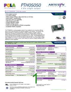
OUTPUT
POWER
(MAX.)
OUTPUT
CURRENT
(MIN.)
OUTPUT
CURRENT
(MAX.)
REGULATION
INPUT
OUTPUT
VOLTAGE
EFFICIENCY
(MAX.)
MODEL
VOLTAGE
NUMBER (9,10)
LINE
10 mV
LOAD
21.6 W
4.5-5.5 Vdc
0.8-3.6 Vdc
0 A
6 A
95%
12 mV
PTH05050
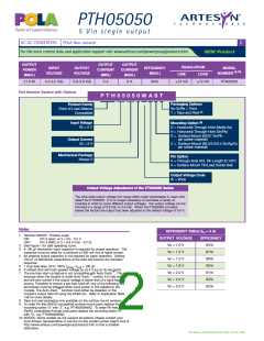
Part Number System with Options
P T H 0 5 0 5 0 W A S T
Packaging Options
No Suffix = Trays
T = Tape and Reel (8)
Product Family
Point of Load Alliance
Compatible
Mounting Option (9)
Input Voltage
05 = 5 V
D = Horizontal Through-Hole (Matte Sn)
H = Horizontal Through-Hole (Sn/Pb)
S = Surface-Mount (63/37 Sn/Pb
pin solder material)
Output Current
05 = 6 A
Z = Surface-Mount (96.5/3.0/0.5 Sn/Ag/Cu
pin solder material)
Mechanical Package
Pin Option
A = Through-Hole Std. Pin Length (0.140”)
A = Surface-Mount Tin/Lead Solder Ball
Always 0
Output Voltage Code
W = Wide
Output Voltage Adjustment of the PTH05050 Series
The ultra-wide output voltage trim range offers major advantages to users who
select the PTH05050. It is no longer necessary to purchase a variety of
modules in order to cover different output voltages. The output voltage can be
trimmed in a range of 0.8 Vdc to 3.6 Vdc. When the PTH05050 converter
leaves the factory the output has been adjusted to the default voltage of 0.8 V.
Notes
EFFICIENCY TABLE (IO = 4 A)
1
Remote ON/OFF. Positive Logic
OUTPUT VOLTAGE
Vo = 1.0 V
EFFICIENCY
85%
ON:
OFF:
Pin 3 open; or V > Vin - 0.5 V
Pin 3 GND; or V < 0.8 V (min - 0.2 V).
2
3
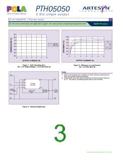
See Figure 1 for safe operating curve.
A 100 µF electrolytic input capacitor is required for proper operation. The
capacitor must be rated for a minimum of 300 mA rms of ripple current.
An external output capacitor is not required for basic operation. Adding
100 µF of distributed capacitance at the load will improve the transient
response.
Vo = 1.2 V
87%
4
Vo = 1.5 V
89%
Vo = 1.8 V
90%
5
6
7
1 A/µs load step, 50 to 100% I
If utilized Vout will track applied voltage by 0.3 V (up to Vo set point).
, C
= 100 µF.
omax
out
™
Vo = 2.0 V
91%
The pre-bias start-up feature is not compatible with Auto-Track . This is
because when the module is under Auto-Track control, it is fully active
™
Vo = 2.5 V
93%
and will sink current if the output voltage is below that of a back-feeding
source. Therefore to ensure a pre-bias hold-off, one of the following two
techniques must be followed when input power is first applied to the
Vo = 3.3 V
95%
™
module. The Auto-Track function must either be disabled, or the
module’s output held off using the Inhibit pin. Refer to Application Note
158 for more details.
Tape and reel packaging only available on the surface-mount versions.
To order Pb-free (RoHS compatible) surface-mount parts replace the
mounting option ‘S’ with ‘Z’, e.g. PTH05050WAZ. To order Pb-free
(RoHS compatible) through-hole parts replace the mounting option ‘H’
with ‘D’, e.g. PTH05050WAD.
8
9
10 NOTICE: Some models do not support all options. Please contact your
local Artesyn representative or use the on-line model number search tool at
http://www.artesyn.com/powergroup/products.htm to find a suitable
alternative.
File Name: pth05050.pdf Rev (06): 16 Dec 2005

 ARTESYN [ ARTESYN TECHNOLOGIES ]