LOW TO MEDIUM POWER AC/DC POWER SUPPLIES
|
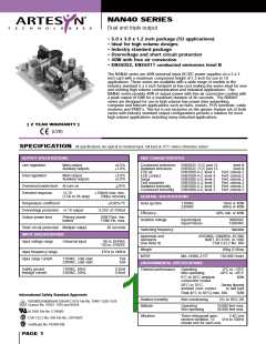
40W AC/DC
40 Watt
AC/DC unive rs al input s witch m ode powe r s upplie s
OUTPUT CURRENT
OUTPUT
VOLTAGE
TOTAL
(B)
(4)
RIPPLE
MODEL NUMBER
(2)
(3)
(5)
MAX (1)
3A
PEAK
7A
FAN
4A
REG.
(5)
+ 5.1V (IA)
+12V (IB)
–12V (IC)
+5.1V (IA)
+12V (IB)
–5V (IC)
50mV
±3.0%
±5.0%
±5.0%
±3.0%
±5.0%
±5.0%
±3.0%
±5.0%
NAN40-7608
2A
3A
2A
120mV
120mV
50mV
0.35A
3A
1A
0.5A
4A
(5)
7A
NAN40-7607
2A
3A
2A
120mV
50mV
0.35A
3A
1.0A
7A
0.5A
4A
(5)
+5.1V (IA)
+12V (IB)
50mV
NAN40-7629
2A
3A
2A
120mV
Notes
Mechanical notes
1
2
Natural convection cooling (40W maximum).
A
Ground pad encircling mounting hole near P1 allows system grounding
through a metal stand-off of up to 8mm max. diameter to metal chassis.
A standard L-bracket and cover is available for mounting, which contains
all screws, connectors and necessary mounting hardware. Order part
number ‘NAL40 COVER KIT’.
Peak output current lasting less than 60 seconds with duty cycle less than
5% . During peak loading, output voltage may exceed total regulation
limits.
B
3
4
Forced air, 20CFM at 1 atmosphere, 50W maximum.
Figure is peak-to-peak. Output noise measurements are made across a
50MHz bandwidth using a 12 inch twisted pair, terminated with a 47µF
capacitor.
5
Total regulation is defined as the static output regulation at 25°C, including
initial tolerance, line voltage within stated limits, load currents within stated
limits and output voltages adjusted to their factory settings. For multiple
output units to maintain stated regulation then:
5.00
(127.00)
0.156 (3.96) Dia. (4 Places)
0.25 ≤ I / I ≤ 5, for I > 0.3A
A
B
B
0.50 ≤ I / I ≤ 5, for I < 0.3A
A
B
B
Minimum load must also be 4W to achieve design MTBF.
J2
For maximum output current I on triple-output models, i.e. for:
= IMax., then I min. ≥ 0.5A and I ≥ I .
A B C
C
F1
1
I
F3.15A, 250VAC
C
6
Derating curve is application specific for ambient temperatures >50°C, for
optimum reliability, no part of the heatsink should exceed 120°C, and no
semiconductor case temperature should exceed 130°C.
3.00
(76.20)
2.55
(64.80)
T1
7
8
Caution: allow a minimum of 1 second after disconnecting line power
when making thermal measurements.
This product is only for inclusion by professional installers within other
equipment and must not be operated as a stand alone product.
1
J1
P1
0.22
(5.59)
4.55
(115.80)
0.22
(5.59)
MAXIMUM COMPONENT
HEIGHT 1.2 inches
ALL DIMENSIONS IN INCHES (mm)
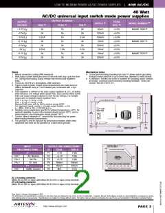
DERATING CURVE (See Notes 6, 7)
INPUT
PIN CONNECTIONS
J 1
OUTPUT PIN CONNECTIONS
Output Power (Watts)
50W
20 CFM FORCED AIR COOLING
J 2
P1
P2
P3
P4
P5
P6
DUAL
+12V
+5.1V
+5.1V
Return
Return
N/C
TRIPLE
V (B)
40W
25W
20W
NATURAL
CONVECTION
COOLING
Pin 1
AC Neutral
No Pin
V (A)
Pin 2
Pin 3
V (A)
AC Line
Return
Return
V (C)
4W
4W MIN. LOAD TO ACHIEVE DESIGN MTBF
P1
Safety Ground
0°C 10°C 20°C 30°C 40°C 50°C 60°C 70°C
Available Output Power V's Ambient Temperature
Pin 1
AC (J 1) mating connector
Molex 09-50-3031 or equiv. with Molex 08-50-0105 or equiv. crimp terminals.
DC (J 2) mating connector
Molex 09-50-3061 or equiv. with Molex 08-50-0164 or equiv. crimp terminals.
Data Sheet © Artesyn Technologies
® 2001
The information and specifications contained in this data sheet are believed to be correct at time of publication. However, Artesyn Technologies accepts no responsibility for consequences arising
from printing errors or inaccuracies. Specifications are subject to change without notice. No rights under any patent accompany the sale of any such product(s) or information contained herein.
http://www.artesyn.com
PAGE 2

 ARTESYN [ ARTESYN TECHNOLOGIES ]