AOZ1232-01
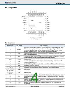
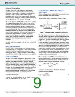
Pin Configuration
30 29 28 27 26 25 24 23
PGOOD
EN
1
2
3
4
5
22 LX
21 LX
AGND
PFM
AGND
FB
20 LX
LX
19 PGND
18 PGND
17 PGND
16 PGND
15 PGND
TON
AIN
6
7
IN
8
9
10 11
12 13 14
30-pin 5mm x 5mm QFN
(Top View)
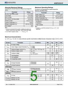
Pin Description
Pin Number
Pin Name
Pin Function
Power Good Signal Output. PGOOD is an open-drain output used to indicate the status
of the output voltage. It is internally pulled low when the output voltage is 10% lower than
the nominal regulation voltage for 50µs (typical time) or 15% higher than the nominal
regulation voltage. PGOOD is pulled low during soft-start and shut down.
1
2
PGOOD
Enable Input. The AOZ1232-01 is enabled when EN is pulled high. The device shuts
down when EN is pulled low.
EN
PFM Selection Input. Connect PFM pin to VCC/VIN for forced PWM operation. Connect
PFM pin to ground for PFM operation to improve light load efficiency.
3
4, 29
5
PFM
AGND
FB
Analog Ground.
Feedback Input. Adjust the output voltage with a resistive voltage-divider between the
regulator’s output and AGND.
6
TON
AIN
IN
On-Time Setting Input. Connect a resistor between VIN and TON to set the on time.
Supply Input for analog functions.
7
8, 9, 10, 11
Supply Input. IN is the regulator input. All IN pins must be connected together.
12, 13, 14, 15, 16,
17, 18, 19, 26
PGND
LX
Power Ground.
Switching Node.
20, 21, 22, 23,
24, 25
Bootstrap Capacitor Connection. The AOZ1232-01 includes an internal bootstrap diode.
Connect an external capacitor between BST and LX as shown in the Typical Application
diagrams.
27
BST
Output for internal linear regulator. Bypass VCC to AGND with a 1µF ceramic capacitor.
Place the capacitor close to VCC pin.
28
30
VCC
SS
Soft-Start Time Setting Pin. Connect a capacitor between SS and AGND to set the
soft-start time.
Rev. 1.3 October 2012
www.aosmd.com
Page 4 of 18

 AOS [ ALPHA & OMEGA SEMICONDUCTORS ]