APL5308/9
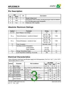
Pin Description
PIN
I/O
Description
No.
Name
1
VIN
I
Supply voltage input.
Ground pins of the circuitry, and all ground pins must be soldered
To PCB with proper power dissipation.
2
3
GND
VOUT
O
Output pin of the regulator.
Absolute Maximum Ratings
Symbol
Parameter
Rating
Unit
IN
OUT
V , V
Input Voltage or Out Voltage
6.5
V
SOT-23 : 260
TH,JA
R
Thermal Resistance – Junction to Ambient
Thermal Resistance – Junction to Case
°C/W
°C/W
SOT-23-5 : 260
SOT-89 :180
SOT-23 : 130
SOT-23-5 : 130
SOT-89 : 38
TH,JC
R
D
J
P
Power Dissipation
Internally Limited
W
T
Operating Junction Temperature
Control Section
°C
0 to 125
0 to 150
-65 to +150
260
Power Transistor
STG
T
Storage Temperature Range
Lead Temperature (Soldering, 10 second)
°C
°C
L
T
Electrical Characteristics
Unless otherwise noted these specifications apply over full temperature, CIN=COUT=1µF, TJ=0 to 125°C.
Typical values refer to TJ=25°C.
APL5308/9
Symbol
Parameter
Input Voltage
Test Conditions
Unit
Min.
Typ. Max.
VIN
2.7
6
V
V
OUT+1.0V< VCC<6.0V, 0mA< IOUT <
VOUT Output Voltage
ILIMIT Circuit Current Limit
SHORT
VOUT -2% VOUT VOUT +2%
V
IN
OUT
V =V +1V
650
mA
mA
mA
mV
mV
I
Short Current
Load Current
VOUT=0V
50
IN
OUT
IOUT
V =V +1V
300
REGLINE Line Regulation
VOUT+1V< VCC<6.0V, IOUT=1mA
VIN =VOUT+1V, 0mA< IOUT < IMAX
1
10
25
Load Regulation
10
REGLOAD
IN
OUT
OUT
V = V +1V , I =1mA-300mA in
Load Transient
150
250
mV
1µs
Copyright ANPEC Electronics Corp.
Rev. A.7 - Mar., 2004
3
www.anpec.com.tw

 ANPEC [ ANPEC ELECTRONICS COROPRATION ]