APA2065
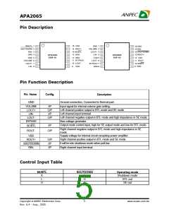
Pin Description
ROUT+ 1
SHUTDOWN 2
RIN- 3
16 VDD
GND 1
16 GND
15 ROUT-
14 SE/BTL
13 GND
VOLUME
2
15 RIN-
LOUT+ 3
14 SHUTDOWN
13 ROUT+
GND 4
GND 5
LIN- 4
APA2065
PDIP-16
APA2065
SOP-16
12 GND
VDD 5
LOUT- 6
BYPASS 7
GND 8
12 VDD
11 ROUT-
10 SE/BTL
9 GND
11 BYPASS
10 LOUT-
VOLUME 6
LOUT+ 7
LIN- 8
9
VDD
Pin Function Description
Pin Name
Config.
Description
GND
Ground connection, Connected to thermal pad.
VOLUME
LOUT+
LIN-
I/P
O/P
I/P
Input signal for internal volume gain setting.
Left channel positive output in BTL mode and SE mode.
Left channel input terminal
Left channel negative output in BTL mode and high impedance in SE mode.
Bias voltage generator
LOUT-
BYPASS
O/P
Output mode control input, high for SE output mode and low for BTL mode.
I/P
SE/BTL
ROUT-
Right channel negative output in BTL mode and high impedance in SE
mode.
O/P
Supply voltage for internal circuit excepting power amplifier.
VDD
Right channel positive output in BTL mode and SE mode.
It will be into shutdown mode when pull low.
ROUT+
O/P
I/P
SHUTDOWN
RIN-
Right channel input terminal
I/P
Control Input Table
SE/BTL
SHUTDOWN
Operating mode
Shutdown mode
BTL out
X
L
H
L
H
H
SE out
Copyright ã ANPEC Electronics Corp.
5
www.anpec.com.tw
Rev. A.4 - Aug., 2005

 ANPEC [ ANPEC ELECTRONICS COROPRATION ]