Model XC0450A-03
Rev B
Mounting
Coupler Mounting Process
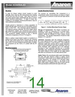
In order for Xinger surface mount couplers to work The process for assembling this component is a
optimally, there must be 50Ω transmission lines leading conventional surface mount process as shown in Figure
to and from all of the RF ports. Also, there must be a 1. This process is conducive to both low and high volume
very good ground plane underneath the part to ensure usage.
proper electrical performance. If either of these two
conditions is not satisfied, electrical performance may not
meet published specifications.
Overall ground is improved if a dense population of
plated through holes connect the top and bottom ground
layers of the PCB. This minimizes ground inductance
Figure 1: Surface Mounting Process Steps
and improves ground continuity. All of the Xinger hybrid
Storage of Components: The Xinger II products are
and directional couplers are constructed from ceramic
available in either an immersion tin or tin-lead finish.
filled PTFE composites which possess excellent electrical
Commonly used storage procedures used to control
and mechanical stability having X and Y thermal
oxidation should be followed for these surface mount
coefficient of expansion (CTE) of 17-25 ppm/oC.
components. The storage temperatures should be held
between 15OC and 60OC.
When a surface mount hybrid coupler is mounted to a
printed circuit board, the primary concerns are; ensuring
the RF pads of the device are in contact with the circuit
Substrate: Depending upon the particular component,
the circuit material has an x and y coefficient of thermal
trace of the PCB and insuring the ground plane of neither
expansion of between 17 and 25 ppm/°C. This coefficient
the component nor the PCB is in contact with the RF
minimizes solder joint stresses due to similar expansion
rates of most commonly used board substrates such as
signal.
RF35, RO4350, FR4, polyimide and G-10 materials.
Mounting to “hard” substrates (alumina etc.) is possible
depending upon operational temperature requirements.
Mounting Footprint
To ensure proper electrical and thermal performance
there must be a ground plane with 100%
solder connection underneath the part
The solder surfaces of the coupler are all copper plated
with either an immersion tin or tin-lead exterior finish.
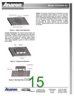
Solder Paste: All conventional solder paste formulations
will work well with Anaren’s Xinger II surface mount
components. Solder paste can be applied with stencils or
syringe dispensers. An example of a stenciled solder
paste deposit is shown in Figure 2. As shown in the
figure solder paste is applied to the four RF pads and the
entire ground plane underneath the body of the part.
.430
[10.92]
Multiple
plated thru holes
to ground
4X .040
[1.02]
.220
[5.59]
4X .065 SQ
Ω
4X 50
[1.65]
Transmission
Line
Dimensions are in Inches [Millimeters]
XC0450A-03* Mounting Footprint
USA/Canada:
Toll Free:
Europe:
(315) 432-8909
(800) 411-6596
+44 2392-232392
Available on Tape and
Reel for Pick and Place
Manufacturing.

 ANAREN [ ANAREN MICROWAVE ]