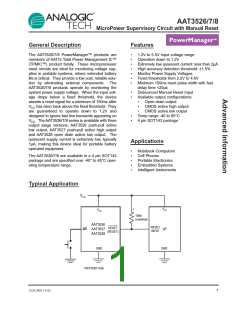
AAT3526/7/8
MicroPower Supervisory Circuit with Manual Reset
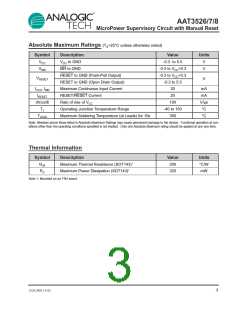
Absolute Maximum Ratings (TA=25°C unless otherwise noted)
Symbol
VCC
Description
Value
-0.3 to 5.5
-0.3 to VCC+0.3
-0.3 to VCC+0.3
-0.3 to 5.5
20
Units
VCC to GND
V
V
VMR
MR to GND
RESET to GND (Push-Pull Output)
RESET to GND (Open Drain Output)
Maximum Continuous Input Current
RESET/RESET Current
VRESET
V
IVCC, IMR
IRESET
dVcc/dt
TJ
mA
mA
V/µs
°C
20
Rate of rise of VCC
100
Operating Junction Temperature Range
Maximum Soldering Temperature (at Leads) for 10s
-40 to 150
300
TLEAD
°C
Note: Stresses above those listed in Absolute Maximum Ratings may cause permanent damage to the device. Functional operation at con-
ditions other than the operating conditions specified is not implied. Only one Absolute Maximum rating should be applied at any one time.
Thermal Information
Symbol
ΘJA
Description
Maximum Thermal Resistance (SOT143)1
Maximum Power Dissipation (SOT143)1
Value
200
Units
°C/W
mW
PD
320
Note 1: Mounted on an FR4 board.
3526.2002.1.0.62
3

 ANALOGICTECH [ ADVANCED ANALOGIC TECHNOLOGIES ]