AAT2557
500mA Battery Charger and 300mA
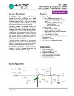
LDO Regulator for Portable Systems
Pin Descriptions
Pin #
Symbol
Function
1
ENLDO
Enable pin for the linear regulator. When connected to logic low, the regulator is dis-
abled and consumes less than 1µA of current. When connected to logic high, it
resumes normal operation.
2, 8, 12, 13, 14
3
GND
BYP
Ground.
Low noise bypass pin. Connect a 10nF capacitor between this pin and ground to
improve AC ripple rejection and reduce noise.
4
5
EN_BAT
ISET
Enable pin for the battery charger. When connected to logic low, the battery charger
is disabled and consumes less than 1µA of current. When connected to logic high,
the charger resumes normal operation.
Charge current set point. Connect a resistor from this pin to ground. Refer to typical
characteristics curves for resistor selection.
6
7
BAT
ADP
Battery charging and sensing.
Input for USB/adapter charger.
9
STAT
Charge status input. Open drain status output.
10
11
OUTLDO
INLDO
Linear regulator output. Connect a 2.2µF capacitor from this pin to ground.
Linear regulator input voltage. Connect a 1µF or greater capacitor from this pin to
ground.
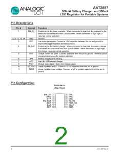
Pin Configuration
TSOPJW-14
(Top View)
1
2
3
4
5
6
7
14
13
12
11
10
9
ENLDO
GND
BYP
EN_BAT
ISET
BAT
GND
GND
GND
INLDO
OUTLDO
STAT
GND
8
ADP
2
2557.2007.06.1.0

 ANALOGICTECH [ ADVANCED ANALOGIC TECHNOLOGIES ]