PRODUCT DATASHEET
AAT2552178
SystemPowerTM
Total Power Solution for Portable Applications
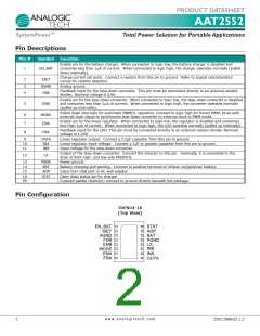
Pin Descriptions
Pin #
Symbol
Function
Enable pin for the battery charger. When connected to logic low, the battery charger is disabled and
consumes less than 1μA of current. When connected to logic high, the charger operates normally (pulled
down internally).
1
EN_BAT
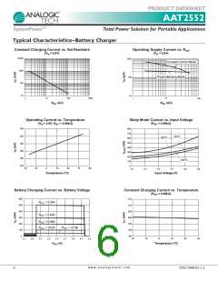
Charge current set point. Connect a resistor from this pin to ground. Refer to typical characteristics
curves for resistor selection.
Analog ground.
Feedback input for the step-down converter. This pin must be connected directly to an external resistor
divider. Nominal voltage is 0.6V.
2
3
4
ISET
AGND
FBB
Enable pin for the step-down converter. When connected to logic low, the step-down converter is disabled
and consumes less than 1μA of current. When connected to logic high, the converter operates normally
(pulled up internally).
5
ENB
Pulled down internally for automatic PWM/LL operation. Connect to logic high for forced PWM. Drive with
external clock signal to synchronize step-down converter to external clock in PWM mode.
Enable pin for the linear regulator. When connected to logic low, the regulator is disabled and consumes
less than 1μA of current. When connected to logic high, the LDO operates normally (pulled up internally).
Feedback input for the LDO. This pin must be connected directly to an external resistor divider. Nominal
voltage is 1.24V.
6
7
8
MODE
ENA
FBA
9
10
11
OUTA
INA
INB
Linear regulator output. Connect a 2.2μF capacitor from this pin to ground.
Linear regulator input voltage. Connect a 1μF or greater capacitor from this pin to ground.
Input voltage for the step-down converter.
Output of the step-down converter. Connect the inductor to this pin. Internally, it is connected to the
drain of both high- and low-side MOSFETs.
12
LX
13
14
15
16
EP
PGND
BAT
ADP
Power ground.
Battery charging and sensing. Connect to positive terminal of Lithium-ion/polymer battery.
Input from USB port or AC wall adapter.
Open drain status pin for charger.
STAT
Exposed paddle (bottom): connect to ground directly beneath the package.
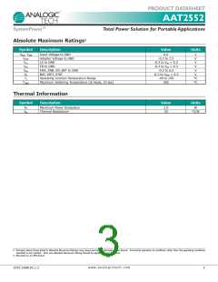
Pin Configuration
TDFN34-16
(Top View)
1
2
3
4
5
6
7
8
16
STAT
ADP
BAT
PGND
LX
INB
INA
EN_BAT
ISET
15
14
13
12
11
10
9
AGND
FBB
ENB
MODE
ENA
FBA
OUTA
w w w . a n a l o g i c t e c h . c o m
2
2552.2008.02.1.2

 ANALOGICTECH [ ADVANCED ANALOGIC TECHNOLOGIES ]