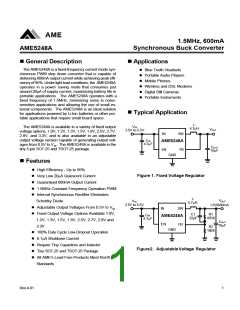
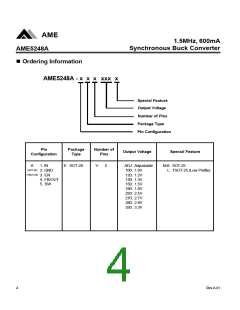
AME
1.5MHz, 600mA
Synchronous Buck Converter
AME5248A
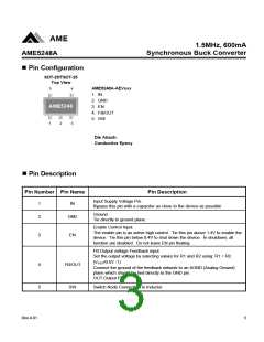
nPin Configuration
SOT-25/TSOT-25
Top View
5
4
AME5248A-AEVxxx
1. IN
2. GND
AME5248
3. EN
4. FB/OUT
5. SW
1
2
3
Die Attach:
Conductive Epoxy
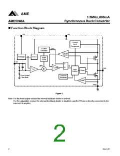
nPin Description
Pin Number Pin Name
Pin Description
Input Supply Voltage Pin.
Bypass this pin with a capacitor as close to the device as possible
1
2
IN
Ground
Tie directly to ground plane.
GND
Enable Control Input.
The enable pin is an active high control. Tie this pin above 1.4V to enable the
device. Tie this pin below 0.4V to shut down the device. In shutdown, all
function are disabled. Do not leave EN pin floating.
3
EN
FB:Output voltage Feedback input.
Set the output voltage by selecting values for R1 and R2 using: R1 = R2
(VOUT/0.5V -1)
4
5
FB/OUT
SW
Connect the ground of the feedback network to an AGND (Analog Ground)
plane which should be tied directly to the GND pin.
OUT:Output Pin
Switch Node Connection to Inductor.
Rev.A.01
3

 AME [ ANALOG MICROELECTRONICS ]