AME, Inc.
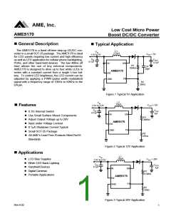
Low Cost Micro Power
Boost DC/DC Converter
AME5170
n Absolute Maximum Ratings
Parameter
Input Supply Voltage
EN, FB Voltages
Symbol
VIN
Maximum
Unit
V
6
VIN
EN,VFB
VSW
V
SW Voltage
VOUT + 0.3
600
V
N-Channel Switch Sink Current
ESD Classification
ISW
mA
B*
Caution: Stress above the listed absolute rating may cause permanent damage to the device.
* HBM B: 2000~3999V
n Recommented Operating Conditions
Parameter
Ambient Temperature Range
Junction Temperature Range
Storage Temperature Range
Symbol
Rating
- 40 to 85
- 40 to 125
- 65 to 150
Unit
TA
TJ
OC
TSTG
n Thermal Information
Parameter
Package
Die Attach
Symbol
Maximum
Unit
Thermal Resistance*
(Junction to Case)
81
qJ
C
oC / W
SOT-25
TSOT-25
Thermal Resistance
(Junction to Ambient)
Conductive Epoxy
260
qJA
Internal Power Dissipation
Solder Iron (10Sec)**
PD
400
350
mW
oC
* Measure qJC on backside center of molding compund if IC has no tab.
** MIL-STD-202G 210F
Rev.A.02
5

 AME [ ANALOG MICROELECTRONICS ]