AME, Inc.
High Power BiPolar Linear LDO
AME1505
n Application Description
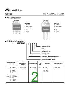
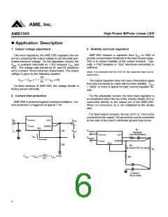
1. Output voltage adjustment
3. Stability and load regulation
AME1505 requires a capacitor from V
provide compensation feedback to the internal gain stage.
This is to ensure stability at the output terminal. Typi-
cally, a 10mF tantalum or 50mF aluminum electrolytic is
sufficient.
to GND to
Like most regulators, the AME1505 regulates the out-
put by comparing the output voltage to an internally gen-
erated reference voltage. On the adjustable version, the
VREF is available externally as 1.25V between VOUT and
ADJ. The voltage ratio formed by R1 and R2 should be
set to conduct 10mA (minimum output load). The output
voltage is given by the following equation:
OUT
(Note: It is important that the ESR for this capacitor does not ex-
ceed 0.5W.)
R2
VOUT = VREF ( 1 +
) + IADJ x R2
The output capacitor dose not have a theoretical upper
limit and increasing its value will increase stability. COUT
= 100mF or more is typical for high current regulator de-
sign.
R1
On fixed versions of AME1505, the voltage divider is
factory-preset internally.
2. Current limit protection
For the adjustable version, the best load regulation is
accomplished when the top of the resistor divider (R1) is
connected directly to the output pin of the AME1505.
AME1505 is protected against overload conditions. Cur-
rent protection is triggered at typical 7.5A.
When so connected, R is not multiplied by the divider
P
ratio.
For fixed output versions, the top of R1 is internally
connected to the output. The ground pin can be connected
to low side of the load to eliminate ground loop errors.
VCONTROL
VPOWER
VIN
OUT
VOUT
SENSE
ADJ
RP
VCONTROL
R1
R2
VREF
C1
Parasitic
Line Resistance
VCONTROL
VPOWER
OUT
IADJ
VPOWER
SENSE
ADJ
R1
(Connect R1 to case)
RL
R2
R1
) + IADJ x R2
VOUT = VREF (1+
R2
Connect
R2 to load
6

 AME [ ANALOG MICROELECTRONICS ]