Analog Microelectronics, Inc.
3A Low Dropout
Positive Voltage Regulator
AME1085
3. Current limit protection
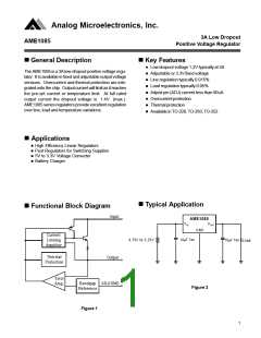
n Application Description
AME1085 is protected against overload condi-
tions. Current protection is triggered at typi-
cally 4.5A.
1. Output voltage adjustment
Like most regulators, the AME1085 regulates the
output by comparing the output voltage to an
internally generated reference voltage. On the
adjustable version, the VREF is available exter-
nally as 1.25V between VOUT and ADJ. The
voltage ratio formed by R1 and R2 should be
4. Stability and load regulation
AME1085 requires a capacitor from VOUT to
GND to provide compensation feedback to the
internal gain stage. This is to ensure stability
at the output terminal. Typically, a 10µF tanta-
lum or 50µF aluminum electrolytic is sufficient.
set
to conduct 10mA (minimum output load).
The output voltage is given by the following
equation:
R2
Note: It is important that the ESR for this ca-
pacitor does not exceed 0.5Ω.
VOUT = VREF ( 1 +
) + IADJ x R2
R1
On fixed versions of AME1085, the voltage di-
vider is provided internally.
The output capacitor dose not have a theoreti-
cal upper limit and increasing its value will in-
creasestability. COUT = 100µF or more is typi-
cal for high current regulator design.
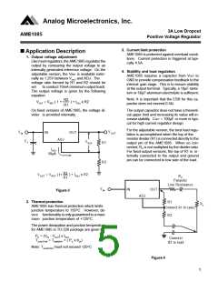
For the adjustable version, the best load regu-
lation is accomplished when the top of the
resistor divider (R1) is connected directly to the
output pin of the AME1085. When so con-
nected, RP is not multiplied by the divider ratio.
For fixed output versions, the top of R1 is in-
ternally connected to the output and ground
pin can be connected to low side of the load.
VOUT
VIN
IN
OUT
ADJ
C1
VREF
R1
R2
IADJ
50
µ
A
R2
R1
) + IADJ x R2
VOUT = VREF (1+
RP
Parasitic
Line Resistance
VIN
IN
OUT
Figure 3
ADJ
2. Thermal protection
R1
RL
AME1085 has thermal protection which limits
junction temperature to 150OC. However, de-
vice functionality is only guaranteed to a maxi-
mum junction temperature of +125OC.
(Connect R1 to case)
R2
The power dissipation and junction temperature
for AME1085 in TO-220 package are given by
PD = (VIN - VOUT) x IOUT
TJUNCTION = TAMBIENT + ( PD x θJA)
Connect
R2 to load
Note: TJUNCTION must not exceed 125OC
Figure 4
5

 AME [ ANALOG MICROELECTRONICS ]