modified buffer point into the third descriptor, then
the controller will complete the frame in buffer num-
ber 2 and then skip the then unowned third buffer.
In this case, the controller will not have had the op-
portunity to RESET the ENP bit in this descriptor,
and it is possible that the software left this bit as
ENP = 1 from the last time through the ring. There-
fore, the software must treat the location as a don’t
care. The rule is, after finding ENP = 1 (or ERR = 1)
in descriptor number 2, the software must ignore
ENP bits until it finds the next STP = 1.
*Same as note in example 2 above, except that in this
case, it is very unlikely that the driver can respond to
the interrupt and get the pointer from the application
before the controller has completed its poll of the next
descriptors. This means that for almost all occurrences
of this case, the controller will not find the OWN bit set
for this descriptor and, therefore, the ENP bit will al-
most always contain the old value, since the controller
will not have had an opportunity to modify it.
**Note that even though the controller will write a
ZERO to this ENP location, the software should treat
the location as a don’t care, since after finding the ENP
= 1 in descriptor number 2, the software should ignore
ENP bits until it finds the next STP = 1.
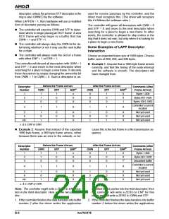
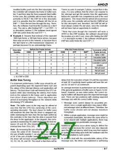
n Example 3: Assume that instead of the expected
1060 byte frame, a 100 byte frame arrives, because
there was an error in the network, or because this is
the last frame in a file transmission sequence, or
perhaps because it is an acknowledge frame.
Before the Frame Arrives
Descriptor
After the Frame Arrives
Comments (After
Number
OWN
STP
ENPa
OWN
STP
ENPb
Frame Arrival)
1
2
3
1
1
0
1
0
0
x
X
X
0
0
0
1
0
0
0
0**
?
Bytes 1-800
Discarded buffer
Discarded buffer
Controller’s current
4
1
1
X
1
1
X
location
5
6
1
0
1
0
0
1
X
X
X
1
0
1
0
0
1
X
X
X
Not yet used
Not yet used
Net yet used
etc.
a. & b.ENP or ERR.
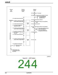
delay from the execution of task C9 until the execution
of task S8. A perfectly timed system will have the val-
ues for S5 and S7 at a minimum.
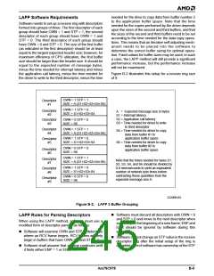
Buffer Size Tuning
For maximum performance, buffer sizes should be ad-
justed depending upon the expected frame size and
the values of the interrupt latency and application call
latency. The best driver code will minimize the CPU uti-
lization while also minimizing the latency from frame
end on the network to the frame sent to application
from driver (frame latency). These objectives are
aimed at increasing throughput on the network while
decreasing CPU utilization.
An average increase in performance can be achieved,
if the general guidelines of buffer sizes in Figure 2 is fol-
lowed. However, as was noted earlier, the correct siz-
ing for buffers will depend upon the expected message
size. There are two problems with relating expected
message size with the correct buffer sizing:
1. Message sizes cannot always be accurately pre-
dicted, since a single application may expect differ-
ent message sizes at different times. Therefore, the
buffer sizes chosen will not always maximize
throughput.
Note: The buffer sizes in the ring may be altered at
any time that the CPU has ownership of the corre-
sponding descriptor. The best choice for buffer sizes
will maximize the time that the driver is swapped out,
while minimizing the time from the last byte written by
the controller to the time that the data is passed from
the driver to the application. In the diagram, this corre-
sponds to maximizing S0, while minimizing the time be-
tween C9 and S8. (the timeline happens to show a
minimal time from C9 to S8.)
2. Within a single application, message sizes might be
somewhat predictable, but when the same driver is
to be shared with multiple applications, there may
not be a common predictable message size.
Additional problems occur when trying to define the
correct sizing because the correct size also depends
upon the interrupt latency, which may vary from system
to system, depending upon both the hardware and the
software installed in each system.
Note: By increasing the size of buffer number 1, we in-
crease the value of S0. However, when we increase
the size of buffer number 1, we also increase the value
of S4. If the size of buffer number 1 is too large, then
the driver will not have enough time to perform tasks
S2, S3, S4, S5, and S6. The result is that there will be
In order to deal with the unpredictable nature of the
message size, the driver can implement a self-tuning
Am79C978
B-7

 AMD [ AMD ]