AMD
MAC (80188
Restrictions — Some of the Am79C930 device 80188
core’s memory locations have predefined uses and,
P R E L I M I N A R Y
Resources
core)
Memory
therefore, are not freely available to the firmware. The
following table indicates restricted space within the
80188 core memory map of the Am79C930 device:
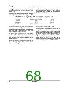
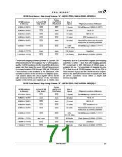
Restricted Space In The 80188 Core Memory Map Using Scheme RAS or RBS,
LMCS=1FF8h, UMCS=E038h, MIR0[7]=0 or 1
80188 Address
in Memory
Active 80188
Chip Select
Size of
Space
Physical Location of Memory
0 0440h–0 047Fh
LCS
64 bytes
Reserved for future use – DO NOT access these
locations
F FC00h–F FFEFh
UCS
1K–16 bytes
Flash Memory 1 FC00h–1 FFEFh
These locations are reserved for use as PCMCIA CIS or
for use as ISA Plug and Play Resource Data, depending
upon the operating mode of the device. These locations
must not be used by the 80188 firmware.
Flash Memory 1 FFF0h–1 FFFFh
F FFF0h–F FFFFh
UCS
16 bytes
These locations must be used to store the first
instructions for the 80188 firmware, since the 80188
core’s instruction pointer will point to location F FFF0h
after a Am79C930 reset. (Note that 80188 location F
FFF0h will appear as 1 FFF0h on the memory interface
bus, since only 17 address bits are available at the
memory interface bus.)
total:
1 Kbytes
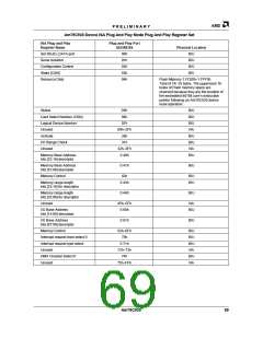
MAC (80188 core) Interrupt Channel Allocation —
The TAI and BIU sections of the Am79C930 device both
generate interrupts to the 80188 core. TAI generated in-
terrupts will always appear on the INT0 input of the
80188core. BIUgeneratedinterruptswillalwaysappear
on the INT1 input of the 80188 core. Firmware should
appropriately recognize the source of each interrupt.
device to allow an interrupt to be generated to the
Am79C930 device’s internal 80188 core.
The BIU sourced interrupts are created by software ma-
nipulation, i.e., a bit in the driver software’s I/O space is
written to, and this in turn generates an interrupt to the
80188 microcontroller within the Am79C930 device.
In summary, the embedded 80188 controller can be in-
terrupted from any of several sources: driver software,
internally generated interrupt sources, and from an ex-
ternal source through the USER1/IRQ12 pin.
Interrupt Channel Allocation in the 80188 Core
80188 Interrupt Channel
Interrupt Source
INT0
INT1
TAI
BIU
MAC (80188 core) DMA Channel Allocation — The
TAIsectionoftheAm79C930devicegeneratesDMAre-
quests to the 80188 core whenever either the transmit
FIFO (TX FIFO) or the receive FIFO (RX FIFO) of the
TAI needs servicing. DRQ0 becomes asserted when-
ever the RX FIFO is NOT empty, regardless of the state
oftheRXSbitofTIR16. DRQ1becomesassertedwhen-
ever the TX FIFO isnot full, regardless of the state of the
TXS bit of TIR8. Appropriate programming of the DMA
resources of the 80188 embedded controller is required
inordertoinsureproperresponsetotheserequests. For
example, when no TX operation is desired, then the
DMA controller for DRQ1 should be disabled.
The interrupt mode used by the 80188 core should be
Master Mode Fully Nested, since no subunit of the
Am79C930 device would respond to 80188 Interrupt
Acknowledge cycles if they occurred. Note that when
using the Master Mode Fully Nested interrupt mode of
the 80188 core, no Interrupt Acknowledge cycles are
generated; instead, the interrupt vector for each inter-
rupt is generated internally. Internally generated
interrupt vectors reside in the lower portion of 80188
memory space.
TAI sourced interrupts may occur due to various condi-
tions that are signaled by TAI internal state machines.
TheTIR4andTIR5registerscontainmostofthebitsthat
signal the various state-machine generated interrupts.
The TCR11 location contains a few more interrupt
sources. One of the TCR11 interrupt sources is through
an external pin, USER1/IRQ12. This allows the user to
connect an external interrupt source to the Am79C930
Note that the use of the 80188 controller’s DMA re-
sources is not required for any given Am79C930-based
implementation, since both the RX FIFO and the TX
FIFO are directly accessible as registers. That is, it is
possible to use 80188 MOV instructions to load TX data
into the TX FIFO. The TX FIFO may be loaded by writing
72
Am79C930

 AMD [ AMD ]