AMD
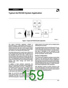
1. Command and status communication
2. Data buffer areas
After waiting for appropriate timing intervals as specified
in the IEEE 802.11 (draft) and the Xircom Netwave stan-
dards, the Am79C930 80188 core will write the transmit
command to the TAI, and the TAI will begin sending the
transmit data stream to the transceiver. During the
transmission procedure, the TX FIFO will require occa-
sional refilling. The request for additional TX data will be
acknowledged by the Am79C930 80188 core until the
entire TX frame has been sent to the transceiver.
When the last byte of data has been sent, a Cyclic
Redundancy Check (CRC) field will automatically be
appended to the frame by the TAI unit when the CRC
function has been enabled. Preamble and Start of
Frame Delimiters will not be automatically generated by
the TAI unit and, therefore, must be supplied by the firm-
ware as part of the data that is loaded into the TX FIFO.
CRC bytes are automatically appended by the TAI after
the TX FIFO empties.
3. Am79C930 80188 core variable space
After performing these functions, the device driver will
enable the 80188 core by writing to a register to release
the RESET of the Am79C930 80188 core. The
Am79C930 80188 core will then begin fetching instruc-
tions from the Flash memory and will eventually execute
code that causes it to recognize the command area that
the driver has set up in the SRAM.
The Am79C930 80188 core will begin by initializing reg-
isters contained within the TAI unit. Once this has been
completed, status will be written to the SRAM command
and status area, and an interrupt will be sent first to the
systeminterface’sstatusregisterandthentothesystem
interface bus. The device driver will acknowledge and
clear the interrupt, and then will write the next command
to the SRAM command and status area, setting an inter-
rupt for the Am79C930 80188 core.
When all bytes, including CRC bytes, have been sent to
the transceiver, TX status information will be gathered
and placed in the SRAM for delivery to the device driver.
Then, an interrupt to the system will be generated.
Flash memory information for system configuration
(PCMCIA CIS or ISA Plug and Play Resource Data) will
normally be pre-programmed in the Flash memory
along with network ID; however, this information may be
written to the Flash memory the first time through the
system interface, before the RESET of the Am79C930
80188 core is released.
Frame Reception
Frame reception is initiated by the network. When the
appropriate network signaling is recognized (a Pream-
ble plus Start of Frame Delimiter) in the TAI unit, the TAI
will begin placing received data into the receive (RX)
FIFO. As the RX FIFO becomes filled with data, it will re-
quest that data be removed by asserting the DMA chan-
nel 0 input of the Am79C930 80188 core. The 80188
core will move the received data from the RX FIFO into
the SRAM data buffer space and will examine the desti-
nation address. If the address does not match the ad-
dress of the Am79C930 subsystem, then the frame will
be rejected by the Am79C930 device. If the frame ad-
dress does match the address of the Am79C930
subsystem, then the frame will be accepted. When all
bytes of the receive frame have been placed into the
SRAM’s data buffer space and the receive status has
been placed into the SRAM, the Am79C930 80188 core
will send an interrupt to the system. The device driver
will respond to the interrupt by reading the command
and status area of the SRAM. Then the device driver will
move the received frame from the SRAM into the sys-
tem memory. Finally, the device driver will write status to
the SRAM to release the data buffer back to the
Am79C930 80188 core for use in a later reception.
Note: Normal system configuration utilities must be dis-
abled before this is attempted.
Frame Transmission
Frame transmission is initiated by the device driver. The
device driver first places the frame data into the SRAM
in the transmit data buffer area. Then the device driver
writes the appropriate set of transmit commands to the
command area of the SRAM and sets an interrupt bit in
one of the system interface registers. An interrupt to the
Am79C930 80188 core will be generated, and the
Am79C930 80188 core will respond by examining the
command area of the SRAM. The transmit command
will instruct the Am79C930 80188 core to move the
transmit data from the data buffer area of SRAM into the
TAI unit’s transmit (TX) FIFO. The move may be accom-
plished either through the use of programmed I/O
moves or DMA moves. DMA channel 1 of the 80188
core is reserved for use by the TX FIFO.
A-2
Am79C930

 AMD [ AMD ]