Revision 1.02 – June 27, 2006
S5935 – PCI Product
Data Book
Asynchronous Register Accesses
For synchronous reads (Figure 3), data is driven onto
the data bus when RD# (or RDFIFO#) is asserted.
When RD# is not asserted, the DQ[31:0] outputs float.
The address, byte enable, and RD# inputs must meet
setup and hold times relative to the rising edge of
BPCLK. Burst reads may be performed by holding
RD# low.
For many Add-On applications, Add-On logic does not
operate at the PCI bus frequency. This is especially
true for Add-Ons implementing a microprocessor,
which may be operating at a lower (or higher) fre-
quency. Figures 1 and 2 show asynchronous Add-On
Operation Register accesses. Exact AC timings are
detailed in the Electrical and AC Characteristics chap-
ter (Chapter 13).
For synchronous writes (Figure 4), data is clocked into
the register on the rising edge of BPCLK. Address,
byte enables, and data must all meet setup and hold
times relative to the rising edge or BPCLK. Burst
writes may be performed by holding WR# (or
WRFIFO#) low. When holding WR# low, data is
clocked in on each BPCLK rising edge.
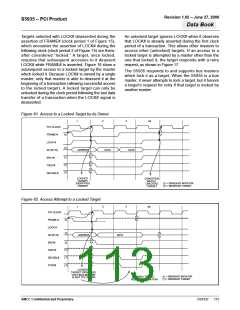
For asynchronous reads (Figure 1), data is driven on
the data bus when RD# is asserted. When RD# is not
asserted, the DQ[31:0] outputs float. A valid address
and valid byte enables must be presented before cor-
rect data is driven. RD# has both a minimum inactive
time and a minimum active time for asynchronous
accesses.
nv Memory Accesses Through the Add-On Gen-
eral Control/Status Register
For asynchronous writes (Figure 2), data is clocked
into the S5935 on the rising edge of the WR# input.
Address, byte enables, and data must all meet setup
and hold times relative to the rising edge or WR#.
WR# has both a minimum inactive time and a mini-
mum active time for asynchronous accesses.
To access nv memory contents through the Add-On
General Control/Status Register (AGCSTS), special
considerations must be made. Internally, all nv mem-
ory accesses by the S5935 are synchronized to a
divided-down version of the PCI bus clock. Because of
this, if nv memory accesses are performed through the
AGCSTS register, the register access must be syn-
chronized to BPCLK. The rising edge RD# or WR# is
still used to clock data, but these inputs along with the
address and byte enables are synchronized to
BPCLK. Accesses to AGCSTS for monitoring FIFO or
mailbox status, etc., may be done asynchronous to
BPCLK.
Synchronous FIFO and Pass-Thru Data Register
Accesses
To obtain the highest data transfer rates possible, Add-
On logic should operate synchronously with the PCI
clock. The buffered PCI clock (BPCLK) is provided for
this purpose. A synchronous interface with Pass-Thru
mode or the FIFO allows data to be transferred at the
maximum PCI bus bandwidth (132 MBytes/sec) by
allowing burst accesses with the Add-On interface.
The RD# and WR# inputs become enables, using
BPCLK to clock data into and out of registers. This
section applies only to synchronous accesses to the
FIFO (AFIFO) and Pass-Thru Data (APTD) registers.
MAILBOX BUS INTERFACE
The mailbox register names may need some clarifica-
tion. For the Add-On interface, an outgoing mailbox
refers to a mailbox sending information to the PCI bus.
An incoming mailbox refers to a mailbox receiving
information from the PCI bus. An outgoing mailbox on
the Add-On interface is, internally, the same as the
corresponding incoming mailbox on the PCI interface
and vice-versa.
Figures 3 and 4 show single-cycle, synchronous FIFO
and Pass-Thru Operation Register accesses. Exact
AC timings are detailed in the Electrical and AC Char-
acteristics chapter.
AMCC Confidential and Proprietary
DS1527
117

 AMCC [ APPLIED MICRO CIRCUITS CORPORATION ]