E4 FRAMING
BLOCK DESCRIPTIONS
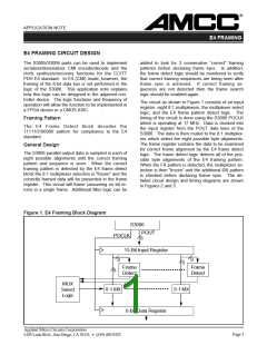
inputs are connected to each of the eight possible
locations of the framing pattern.
Input Register: 15-bit register which holds all the
possible positions of the unframed data. The bit
position of the data in this register is dependent on
the random alignment of the data outputs of the
S3006.
Multiplexer Select Logic: This block takes in the
results of all the decoder blocks and outputs the cor-
rect 8:1 multiplexer select values.
8:1 Multiplexers: These eight multiplexers select the
data alignment to be clocked into the data register.
Data Register: This block contains the correctly
framed data after frame alignment has occurred.
Frame Detect: These are 8 wide decoders which
decode the 111110100000 E4 framing pattern. The
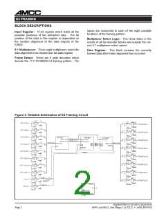
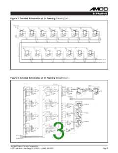
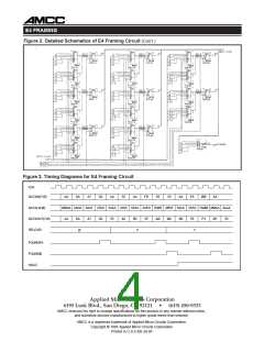
Figure 2. Detailed Schematics of E4 Framing Circuit
Applied Micro Circuits Corporation
Page 2
6195 Lusk Blvd., San Diego, CA 92121 • (619) 450-9333

 AMCC [ APPLIED MICRO CIRCUITS CORPORATION ]