MAX 7000 Programmable Logic Device Family Data Sheet
For more information on using the Jam language, see Application Note 88
(Using the Jam Language for ISP & ICR via an Embedded Processor).
f
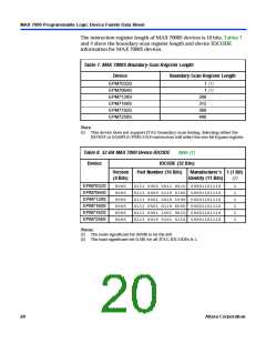
The ISP circuitry in MAX 7000S devices is compatible with IEEE Std. 1532
specification. The IEEE Std. 1532 is a standard developed to allow
concurrent ISP between multiple PLD vendors.
MAX 7000 devices offer a power-saving mode that supports low-power
operation across user-defined signal paths or the entire device. This
feature allows total power dissipation to be reduced by 50% or more,
because most logic applications require only a small fraction of all gates to
operate at maximum frequency.
Programmable
Speed/Power
Control
The designer can program each individual macrocell in a MAX 7000
device for either high-speed (i.e., with the Turbo BitTM option turned on)
or low-power (i.e., with the Turbo Bit option turned off) operation. As a
result, speed-critical paths in the design can run at high speed, while the
remaining paths can operate at reduced power. Macrocells that run at low
power incur a nominal timing delay adder (tLPA) for the tLAD, tLAC, tIC
tEN, and tSEXP, tACL, and tCPPW parameters.
,
MAX 7000 device outputs can be programmed to meet a variety of
system-level requirements.
Output
Configuration
MultiVolt I/O Interface
MAX 7000 devices—except 44-pin devices—support the MultiVolt I/ O
interface feature, which allows MAX 7000 devices to interface with
systems that have differing supply voltages. The 5.0-V devices in all
packages can be set for 3.3-V or 5.0-V I/ O pin operation. These devices
have one set of VCCpins for internal operation and input buffers
(VCCINT), and another set for I/ O output drivers (VCCIO).
The VCCINTpins must always be connected to a 5.0-V power supply.
With a 5.0-V VCCINT level, input voltage thresholds are at TTL levels, and
are therefore compatible with both 3.3-V and 5.0-V inputs.
The VCCIOpins can be connected to either a 3.3-V or a 5.0-V power
supply, depending on the output requirements. When the VCCIOpins are
connected to a 5.0-V supply, the output levels are compatible with 5.0-V
systems. When VCCIO is connected to a 3.3-V supply, the output high is
3.3 V and is therefore compatible with 3.3-V or 5.0-V systems. Devices
operating with VCCIO levels lower than 4.75 V incur a nominally greater
timing delay of tOD2 instead of tOD1
.
Altera Corporation
17

 ALTERA [ ALTERA CORPORATION ]