1–22
Chapter 1: Cyclone IV Device Datasheet
Switching Characteristics
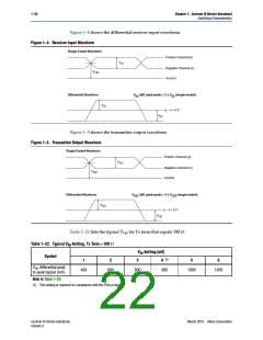
Figure 1–4 shows the differential receiver input waveform.
Figure 1–4. Receiver Input Waveform
Single-Ended Waveform
Positive Channel (p)
V
ID
Negative Channel (n)
V
CM
Ground
Differential Waveform
V
(diff peak-peak) = 2 x V (single-ended)
ID
ID
V
ID
p − n = 0 V
V
ID
Figure 1–5 shows the transmitter output waveform.
Figure 1–5. Transmitter Output Waveform
Single-Ended Waveform
Positive Channel (p)
V
OD
Negative Channel (n)
V
CM
Ground
Differential Waveform
V
(diff peak-peak) = 2 x V
OD
(single-ended)
OD
V
OD
p − n = 0 V
V
OD
Table 1–22 lists the typical VOD for Tx term that equals 100 .
Table 1–22. Typical VOD Setting, Tx Term = 100
VOD Setting (mV)
Symbol
(1)
1
2
3
4
5
6
V
OD differential peak
400
600
800
900
1000
1200
to peak typical (mV)
Note to Table 1–22:
(1) This setting is required for compliance with the PCIe protocol.
Cyclone IV Device Handbook,
Volume 3
March 2016 Altera Corporation

 ALTERA [ ALTERA CORPORATION ]