DC and Switching Characteristics
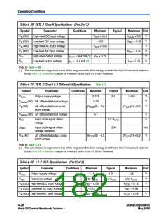
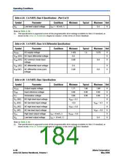
Table 4–32. 1.2-V HSTL Specifications (Part 2 of 2)
Symbol
Parameter
Conditions
Minimum
–0.24
Typical
Maximum
VREF – 0.15
VCCIO + 0.15
VREF – 0.15
Unit
V
VIL (AC) Low-level AC input voltage
VOH
VOL
High-level output voltage
Low-level output voltage
IOH = 8 mA
VREF + 0.15
–0.15
V
IOH = –8 mA
V
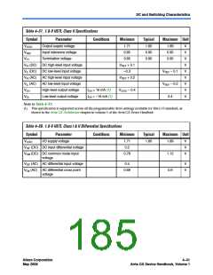
Table 4–33. 1.5-V HSTL Class I Specifications
Symbol
VCCIO
VREF
Parameter
Conditions
Minimum
Typical
Maximum Unit
Output supply voltage
Input reference voltage
Termination voltage
1.425
0.713
1.5
1.575
0.788
0.788
V
V
V
V
V
V
V
V
V
0.75
0.75
VTT
0.713
V
V
V
V
IH (DC)
IL (DC)
IH (AC)
IL (AC)
DC high-level input voltage
DC low-level input voltage
AC high-level input voltage
AC low-level input voltage
High-level output voltage
Low-level output voltage
VREF + 0.1
–0.3
VREF – 0.1
VREF – 0.2
0.4
VREF + 0.2
VOH
VOL
IOH = 8 mA (1)
IOH = –8 mA (1)
VCCIO – 0.4
Note to Table 4–33:
(1) This specification is supported across all the programmable drive settings available for this I/O standard as shown
in the Arria GX Architecture chapter in volume 1 of the Arria GX Device Handbook.
Table 4–34. 1.5-V HSTL Class II Specifications (Part 1 of 2)
Symbol
VCCIO
VREF
Parameter
Conditions
Minimum
1.425
Typical
1.50
Maximum Unit
Output supply voltage
Input reference voltage
Termination voltage
1.575
0.788
0.788
V
V
V
V
V
V
V
V
0.713
0.75
VTT
0.713
0.75
V
V
V
V
IH (DC)
IL (DC)
IH (AC)
IL (AC)
DC high-level input voltage
DC low-level input voltage
AC high-level input voltage
AC low-level input voltage
High-level output voltage
VREF + 0.1
–0.3
VREF – 0.1
VREF – 0.2
VREF + 0.2
VOH
IOH = 16 mA (1)
VCCIO – 0.4
Altera Corporation
May 2008
4–29
Arria GX Device Handbook, Volume 1

 ALTERA [ ALTERA CORPORATION ]