11–10
Chapter 11: SEU Mitigation in the Cyclone III Device Family
Recovering from CRC Errors
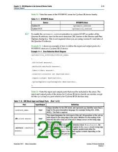
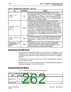
Table 11–8. CRC Block Input and Output Ports (Part 2 of 2)
Port
Input/Output
Definition
This signal is an input into the error detection block. If ldsrc=0, the
pre-computed CRC register is selected for loading into the 32-bit shift register
at the rising edge of clkwhen shiftnld=0. If ldsrc=1, the signature
register (result of the CRC calculation) is selected for loading into the shift
register at the rising edge of clkwhen shiftnld=0. This port is ignored
when shiftnld=1. This port is required.
.ldsrc (<ldsrc
source>)
Input
This signal is the output of the cell that is synchronized to the internal
oscillator of the device (80-MHz internal oscillator) and not to the clkport. It
asserts high if the error block detects that a SRAM bit has flipped and the
internal CRC computation has shown a difference with respect to the pre-
computed value. This signal must be connected either to an output pin or a
bidirectional pin. If it is connected to an output pin, you can only monitor the
CRC_ERROR pin(the core cannot access this output). If the CRC_ERROR
signal is used by core logic to read error detection logic, this signal must be
connected to a BIDIRpin. The signal is fed to the core indirectly by feeding a
BIDIRpin that has its output enable port connected to VCC (Figure 11–3 on
page 11–8).
.crcerror (<crcerror
indicator
Output
output>)
This signal is the output of the error detection shift register synchronized to
the clkport, to be read by core logic. It shifts one bit at each cycle, so you
should clock the clksignal 31 cycles to read out the 32 bits of the shift
register.
.regout (<registered
output>)
Output
Output
This signal is for cycloneiiils_crcblockonly. This output signal is
synchronized to the internal oscillator of the device (80-MHz internal
oscillator), and not to the clkport. The signal asserts high for one clock
cyclone every time an error detection cyclone completes.
.cyclecomplete (<cyclone
complete indicator
output>)
Recovering from CRC Errors
The system that the Altera FPGA resides in must control device reconfiguration. After
detecting an error on the CRC_ERRORpin, strobing the nCONFIGlow directs the system
to perform the reconfiguration at a time when it is safe for the system to reconfigure
the FPGA.
When the data bit is rewritten with the correct value by reconfiguring the device, the
device functions correctly.
While soft errors are uncommon in Altera devices, certain high-reliability applications
might require a design to account for these errors.
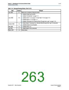
Document Revision History
Table 11–9 lists the revision history for this document.
Table 11–9. Document Revision History (Part 1 of 2)
Date
Version
2.3
Changes
■ Updated “User Mode Error Detection” on page 11–2.
■ Update hyperlinks.
December 2011
December 2009
■ Minor text edits.
2.2
Minor changes to the text.
Cyclone III Device Handbook
Volume 1
December 2011 Altera Corporation

 ALTERA [ ALTERA CORPORATION ]