Chapter 11: SEU Mitigation in the Cyclone III Device Family
11–5
Error Detection Timing
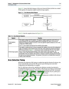
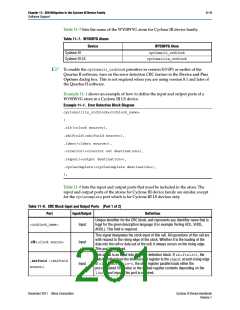
Figure 11–1 shows the block diagram of the error detection block and the two related
32-bit registers: the signature register and the storage register.
Figure 11–1. Error Detection Block Diagram
Control Signals
Error Detection
State Machine
Compute & Compare
CRC
32
32
32-bit Storage
Register
32-bit Signature
Register
32
Table 11–4 lists the registers shown in Figure 11–1.
Table 11–4. Error Detection Registers
Register
Function
This register contains the CRC signature. The signature register contains the result of the user
mode calculated CRC value compared against the pre-calculated CRC value. If no errors are
detected, the signature register is all zeros. A non-zero signature register indicates an error in the
configuration CRAM contents.
32-bit signature
register
The CRC_ERRORsignal is derived from the contents of this register.
This register is loaded with the 32-bit pre-computed CRC signature at the end of the configuration
stage. The signature is then loaded into the 32-bit CRC circuit (called the Compute and Compare
CRC block, as shown in Figure 11–1) during user mode to calculate the CRC error. This register
forms a 32-bit scan chain during execution of the CHANGE_EDREGJTAG instruction. The
CHANGE_EDREGJTAG instruction can change the content of the storage register. Therefore, the
functionality of the error detection CRC circuitry is checked in-system by executing the instruction
to inject an error during the operation. The operation of the device is not halted when issuing the
CHANGE_EDREGinstruction.
32-bit storage register
Error Detection Timing
When the error detection CRC feature is enabled through the Quartus II software, the
device automatically activates the CRC process upon entering user mode after
configuration and initialization is complete.
The CRC_ERRORpin is driven low until the error detection circuitry has detected a
corrupted bit in the previous CRC calculation. After the pin goes high, it remains high
during the next CRC calculation. This pin does not log the previous CRC calculation.
If the new CRC calculation does not contain any corrupted bits, the CRC_ERRORpin is
driven low. The error detection runs until the device is reset.
The error detection circuitry runs off an internal configuration oscillator with a divisor
that sets the maximum frequency.
December 2011 Altera Corporation
Cyclone III Device Handbook
Volume 1

 ALTERA [ ALTERA CORPORATION ]