Interlock Switches
Tongue Switches
Elf
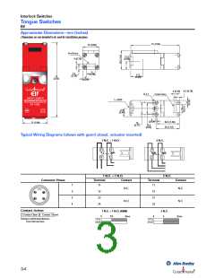
Approximate Dimensions—mm (inches)
Dimensions are not intended to be used for installation purposes.
75 (2.95)
25 (0.98)
End Entry
4 (0.16)
12.5
(0.49)
6
4.5
(0.18)
(0.24)
17.5
(0.69)
75
(2.95)
6
(0.24)
4.5 (0.18)
4 (0.16)
R 2.1
Front Entry
1 x M16
12.5
(0.49)
3
(0.12)
16.5
34.5 (1.36)
36 (1.42)
25 (0.98)
18
(0.71)
(0.65)
Typical Wiring Diagrams (shown with guard closed, actuator inserted)
1 N.C. + 1 N.O.
2 N.C.
23
24
11
12
21
11
12
22
1 N.C. + 1 N.O.
2 N.C.
Connector Pinout
Term inal
Contact
Term inal
Contact
1
3
2
4
11
11
N.C.
N.C.
N.C.
12
23
24
12
21
22
2
3
1
4
N.O.
0mm
Contact Action
Contact Open
1 N.C. + 1 N.O. (BBM)
2 N.C.
Contact Closed
6
3.8
6
11/12
21/22
4
0mm
Actuator withdrawal distance
from full insertion
11/12
23/24
4.2
3-4

 ALLEN-BRADLEY [ Allen-Bradley ]