3240
CHOPPER-STABILIZED,
PRECISION
HALL-EFFECT SWITCH
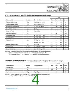
ELECTRICAL CHARACTERISTICS over operating temperature range.
Limits
Typ.
Characteristic
Symbol
Test Conditions
Operating, TJ < 165°C1
VOUT = 24 V, B < BRP
IOUT = 20 mA, B > BOP
B > BOP
Min.
4.2
–
Max.
24
Units
V
Supply Voltage Range
Output Leakage Current
Output Saturation Voltage
Output Current Limit
Power-On Time
VCC
–
–
IOFF
10
µA
VOUT(SAT)
–
185
–
500
60
mV
mA
µs
IOM
tpo
fC
30
VCC
>
4.2
–
Chopping Frequency
Output Rise Time
–
–
–
340
0.2
0.1
kHz
µs
tr
RL = 820 Ω, CL = 20 pF
RL = 820 Ω, CL = 20 pF
B < BRP, VCC
2.0
2.0
Output Fall Time
tf
µs
Supply Current
ICC
=
12
12
V–
V–
3.
4.
B > BOP, VCC
=
Reverse Battery Current
Zener Voltage
ICC
VRCC
=
-30
37
–
VZ + VD
zz + zD
ICC = 15 mA, TA = 25°C
ICC = 15 mA, TA = 25°C
28
–
32
50
V
Zener Impedance
Ω
NOTES:1. Maximum voltage must be adjusted for power dissipation and junction temperature.
2. BOP = operate point (output turns on); BRP = release point (output turns off).
3. Typical Data is at TA = +25°C and VCC = 12 V and is for design information only.
MAGNETIC CHARACTERISTICS over operating supply voltage and temperature ranges.
Limits
Characteristic
Operate Point
Release Point
Hysteresis
Symbol
BOP
Test Conditions
Min.
–
Typ.
35
Max.
50
–
Units
G
BRP
5.0
–
25
G
Bhys
BOP - BRP
10
–
G
NOTES: 1. Typical Data is at TA = +25°C and VCC = 12 V and is for design information only.
2. 1 gauss (G) is exactly equal to 0.1 millitesla (mT).
www.allegromicro.com
4

 ALLEGRO [ ALLEGRO MICROSYSTEMS ]