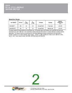
2919
DUAL FULL-BRIDGE
MOTOR DRIVER
LOGIC CONTROL OF OUTPUT CURRENT
GENERAL
Two logic level inputs (l0 and I1) allow digital selection
of the motor winding current at 100%, 67%, 41%, or 0% of
the maximum level per the table. The 0% output current
condition turns OFF all drivers in the bridge and can be
used as an OUTPUT ENABLE function.
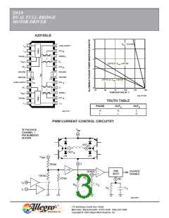
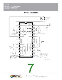
The PHASE input to each bridge determines the
direction motor winding current flows. An internally
generated deadtime (approximately 2 µs) prevents cross-
over currents that can occur when switching the PHASE
input.
All four drivers in the bridge output can be turned OFF
between steps (l0 = l1 ≥ 2.4 V) resulting in a fast current
decay through the internal output clamp and flyback
diodes. The fast current decay is desirable in half-step and
high-speed applications. The PHASE, l0, and I1 inputs
float high.
CURRENT-CONTROL TRUTH TABLE
l0
L
I1
L
Output Current
VREF/10 RS = 100% ITRIP
VREF/15 RS = 67% ITRIP
VREF/24.4 RS = 41% ITRIP
0
H
L
L
H
H
Varying the reference voltage (VREF) provides continu-
ous control of the peak load current for micro-stepping
applications.
H
These logic level inputs greatly enhance the implem-
Thermal protection circuitry turns OFF all drivers when
the junction temperature reaches +170°C. It is only
intended to protect the device from failures due to exces-
sive junction temperature and should not imply that output
short circuits are permitted. The output drivers are re-
enabled when the junction temperature cools to +145°C.
entation of µP-controlled drive formats.
During half-step operations, l0 and l1 allow the µP to
control the motor at a constant torque between all posi-
tions in an eight-step sequence. This is accomplished by
digitally selecting 100% drive current when only one phase
is ON and 67% drive current when two phases are ON.
Logic highs on both l0 and l1 turn OFF all drivers to allow
rapid current decay.
The A2919SB/SLB output drivers are optimized for
low output saturation voltages—less than 1.8 V total
(source plus sink) at 500 mA. Under normal operating
conditions, when combined with the excellent thermal
properties of the batwing package design, this allows
continuous operation of both bridges simultaneously at
500 mA.
During quarter-step operation, I0 and I1 allow the µP to
control the motor position in a sixteen-step sequence.
This is accomplished by digitally selecting drive current as
shown in the table (for one quadrant of operation). Logic
highs on both I0 and I1 turn OFF all drivers to allow rapid
current decay.
The logic control inputs can also be used to select a
reduced current level (and reduced power dissipation) for
‘hold’ conditions and/or increased current (and available
torque) for start-up conditions.
QUARTER-STEPPING CURRENT CONTROL
Phase 1
Phase 2
Current Level
Current Level
100%
100%
67%
41%
0%
0%
41%
67%
100%
100%

 ALLEGRO [ ALLEGRO MICROSYSTEMS ]