Low-Voltage, Full-Bridge Brushless DC Motor Driver with
Integrated Hall Sensor IC, PWM Speed Control, Soft-Switching,
and Reverse Battery and Short Circuit Protection
A1448
Application Information
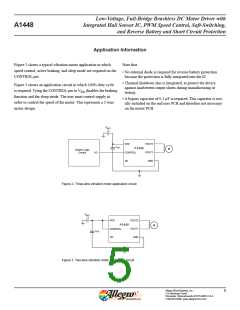
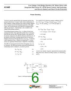
Figure 2 shows a typical vibration motor application in which
speed control, active braking, and sleep mode are required on the
CONTROL pin.
Note that:
• No external diode is required for reverse battery protection
because the protection is fully integrated into the IC.
• Thermal shutdown also is integrated, to protect the device
against inadvertent output shorts during manufacturing or
testing.
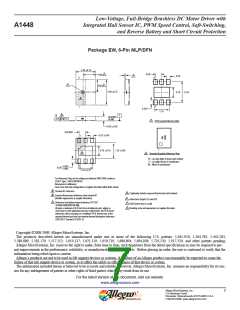
Figure 3 shows an application circuit in which 100% duty cycle
is required. Tying the CONTROL pin to VDD disables the braking
function and the sleep mode. The user must control supply in
order to control the speed of the motor. This represents a 2-wire
motor design.
• A bypass capacitor of 0.1 μF is required. This capacitor is usu-
ally included on the end user PCB and therefore not necessary
on the motor PCB.
VBATT
VDD
VOUT2
VOUT1
GND
CBYP
A1448
M
System Logic
Control
CONTROL
I/O
NC
Figure 2. Three-wire vibration motor application circuit
VBATT
VDD
VOUT2
VOUT1
GND
A1448
M
CONTROL
CBYP
NC
Figure 3. Two-wire vibration motor application circuit
Allegro MicroSystems, Inc.
115 Northeast Cutoff
5
Worcester, Massachusetts 01615-0036 U.S.A.
1.508.853.5000; www.allegromicro.com

 ALLEGRO [ ALLEGRO MICROSYSTEMS ]