[AK4679]
■ ALC Operation
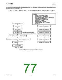
The ALC (Automatic Level Control) is executed by ALC block when ALC bit is “1”. ALC circuit operates at playback
path for Playback mode (Figure 64 and Figure 65) and operates at recording path for Recording mode (Figure 62 and
Figure 63).
1. ALC Limiter Operation
During the ALC limiter operation, when either Lch or Rch exceeds the ALC limiter detection level (Table 28), the IVL
and IVR values (same value) are attenuated automatically by the amount defined by the ALC limiter ATT step (Table 29).
When ZELMN bit = “0” (zero cross detection is enabled), the IVL and IVR values are changed by ALC limiter operation
at the individual zero crossing points of Lch and Rch or at the zero crossing timeout. ZTM1-0 bits set the zero crossing
timeout period of both ALC limiter and recovery operation (Table 30). When ALC output level exceeds full-scale at
LFST bit = “1”, IVL and IVR values are immediately (period: 1/fs) changed in 1 step(L/R common). When ALC output
level is less than full-scale, the IVL and IVR values are changed at the individual zero crossing point of each channels or
at the zero crossing timeout.
When ZELMN bit = “1” (zero cross detection is disabled.), IVL and IVR values are immediately (period: 1/fs) changed
by ALC limiter operation. Attenuation step is fixed to 1 step regardless of the setting LMAT1-0 bits.
The attenuation operation is exceeded continuously until the input signal level becomes ALC limiter detection level
(Table 28) or less. After completing the attenuate operation, unless ALC bit is changed to “0”, the operation repeats when
the input signal level exceeds LMTH1-0 bits.
LMTH1 LMTH0 ALC Limier Detection Level
ALC Recovery Waiting Counter Reset Level
bit
0
0
1
1
bit
0
1
0
1
(default)
ALC Output ≥ −2.5dBFS
ALC Output ≥ −4.1dBFS
ALC Output ≥ −6.0dBFS
ALC Output ≥ −8.5dBFS
−2.5dBFS > ALC Output ≥ −4.1dBFS
−4.1dBFS > ALC Output ≥ −6.0dBFS
−6.0dBFS > ALC Output ≥ −8.5dBFS
−8.5dBFS > ALC Output ≥ −12dBFS
Table 28. ALC Limiter Detection Level / Recovery Counter Reset Level
ALC Limiter ATT Step
LMAT1
LMAT0
bit
ALC Output
≥ LMTH
ALC Output
ALC Output
ALC Output
≥ FS + 12dB
bit
≥ FS
≥ FS + 6dB
0
0
1
1
0
1
0
1
1
2
2
1
1
2
4
2
1
2
4
4
1
2
8
8
(default)
Table 29. ALC Limiter ATT Step
ZTM1
bit
ZTM0
bit
Zero Crossing Timeout Period
8kHz 16kHz 44.1kHz
2.9ms
0
0
1
1
0
1
0
1
128/fs
256/fs
512/fs
1024/fs
16ms
32ms
64ms
128ms
8ms
16ms
32ms
64ms
(default)
5.8ms
11.6ms
23.2ms
Table 30. ALC Zero Crossing Timeout Period
MS1402-E-06
2013/02
- 73 -

 AKM [ ASAHI KASEI MICROSYSTEMS ]