[AK4634]
■ MIC Input Recording
Example:
PLL Master Mode
Audio I/F Format: MSB justified
Sampling Frequency: 44.1kHz
Pre MIC AMP:+20dB
FS3-0 bits
XXXX
XXXX
MIC Power On
(Addr:05H,
ADC Initialize time: 291/fs
ALC1 setting:Refer to Table 34
HPFAD, HPF : ON (fc=150Hz)
5 band EQ : OFF
D5,D2-0)
(1)
ADRST bit
X
X
(1) Addr:05H, Data:A7H
(Addr:05H, D7)
MIC Control
001
1XX
XXH
XXH
XXH
2XH
(2) Addr:02H, Data:05H
(Addr:02H, D2-0)
(2)
ALC1 Control 1
XXH
(3) Addr:06H, Data:70H
(4) Addr:08H, Data:C5H
(5) Addr:09H, Data:C5H
(6) Addr:07H, Data:A1H
(7) Addr:03H, Data:81H
(8-1) Addr:1CH, Data:A9H
(8-2) Addr:1DH, Data:1FH
(8-3) Addr:1EH, Data:53H
(8-4) Addr:1FH, Data:1FH
(9) Addr:11H, Data:11H
(10) Addr:00H, Data:C1H
Recording
(Addr:06H)
(3)
ALC1 Control 2
XXH
(Addr:08H)
(4)
IVOL7-0bits
(Addr:09H)
XXH
(5)
ALC1 Control 3
XXH
(Addr:07H)
(6)
Signal Select
(Addr:03H)
XXH
81H
(7)
Filter Co-ef
(Addr:10H-1F)
XX....X
XX....X
(8)
Filter Select
(Addr:11H D5-4, D0)
XXX1
XXX1
(9)
ALC1 State
ALC1 Disable
ALC1 Disable
ALC1 Enable
PMADC bit
(Addr:00H, D0)
(10)
(11)
PMPFIL bit
(Addr:00H, D7)
291/fs or 1059/fs
ADC Internal
State
Power Down
NormalState Power Down
Initialize
(11) Addr:00H, Data:40H
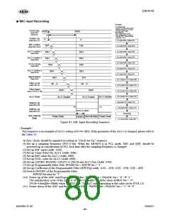
Figure 63. MIC Input Recording Sequence
<Example>
This sequence is an example of ALC1 setting at fs=44.1kHz. If the parameter of the ALC1 is changed, please refer to
the Table 34.
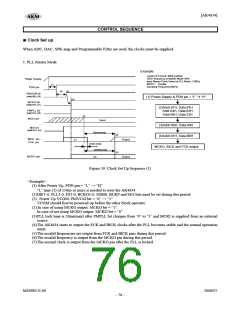
At first, clocks should be supplied according to “Clock Set Up” sequence.
(1) Set up a sampling frequency (FS3-0 bit). When the AK4634 is in PLL mode, MIC and ADC should be
powered-up in consideration of PLL lock time after the sampling frequency is changed.
(2) Set up MIC input (Addr: 02H)
(3) Set up Timer Select for ALC1 (Addr: 06H)
(4) Set up REF value for ALC1 (Addr: 08H)
(5) Set up IVOL value for ALC1 (Addr: 09H)
(6) Set up LMTH0, RGAIN0, LMAT1-0, ZELM and ALC1 bits (Addr: 07H)
(7) Set up Programmable Filter Path: PFSDO bit = ADCPF bit = “1”
(8) Set up Coefficient of the Programmable Filter (HPF/EQ) Addr: 1CH ~ 1FH, 2CH ~ 2FH, 32H ~ 4FH
(9) Switch ON/OFF of the Programmable Filter
HPFAD bit must be “1”.
(10) Power-up of the ADC and Programmable Filter: PMPFIL bit = PMADC bit = “0” Æ “1”
The initialization cycle of the ADC is 1059/fs=24ms@fs=44.1kHz when ADRST bit = “0”,
291/fs=18ms@fs=16kHz when ADRST bit= “1”. ALC starts operating at the value set by IVOL (5).
(11) Power-down of the ADC and Programmable Filter: PMPFIL bit = PMADC bit = “1” Æ “0”
MS0983-E-00
2008/07
- 80 -

 AKM [ ASAHI KASEI MICROSYSTEMS ]