[AK4634]
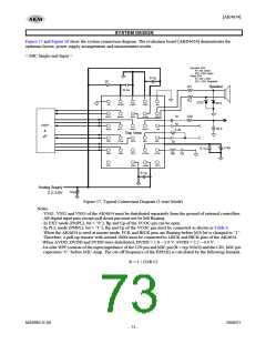
< MIC differential Input >
Dynamic SPK
R1, R2: Short
ZD1, ZD2: Open
Piezo SPK
R1, R2: ≥10Ω
ZD1, ZD2: Required
0.1µ
10
R1
Speaker
0.1µ
R2
ZD2
ZD1
I2C
DVDD
VSS2
SPN
VSS3
SVDD
AOUT
MPI
NC
1µ
220
SDTO
BICK
FCK
MCKO
SDTI
SPP
MICN
MICP
VCOC
TST3
1µ
1k
DSP
&
20 k
MCKI
1k
Top View
µP
CCLK
CSN
CDTI
TST2
VSS1
1µ
+
2.2µ
0.1µ
PDN
VCOM
AVDD
Rp
Cp
TST1
0.1µ
Analog Supply
+
10µ
2.2∼3.6V
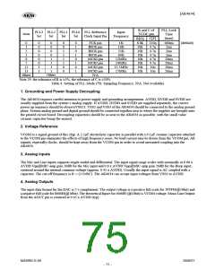
Figure 58. Typical Connection Diagram (3-wire Mode)
Notes:
- VSS1, VSS2 and VSS3 of the AK4634 must be distributed separately from the ground of external controllers.
- All digital input pins except pull-down pin must not be left floating.
- In EXT mode (PMPLL bit = “0”), Rp and Cp of the VCOC pin can be open.
- In PLL mode (PMPLL bit = “1”), Rp and Cp of the VCOC pin must be connected as shown in Table 4.
- When the AK4634 is used at master mode, FCK and BICK pins are floating before M/S bit is changed to “1”.
Therefore, a pull-up resistor with around 100Ω must be connected to LRCK and BICK pins of the AK4634.
-When AVDD, DVDD and SVDD were distributed, DVDD = 1.6 ~ 3.6 V, SVDD = 2.2 ~ 4.0 V.
-1st-oder HPF consists of the input impedance of the MICP pin and MICN pin (R = typ 30 kΩ) and the MICP,
MICN pin capacitors “C” before MIC-Amp. The cut-off frequency of the HPF(fs) is calculated by the
following formula.
fc = 1 / (2πR C)
MS0983-E-00
2008/07
- 74 -

 AKM [ ASAHI KASEI MICROSYSTEMS ]