[AK1572]
4. Block Diagram and Function
Lock
Detect
Dig
LDO
LD
VREF1
REFIN
GND
CP
Charge
Pump
R Counter
8bit
Phase
Frequency
Detector
VIREFGEN
VREF2
GND
CLK
DATA
LE
Fast Counter
Register
24bit
VCOVDD
VCNT
VCO
VCO
Calibration
ΔΣ
Modulator
PVDD
GND
Divider
1/N
N=1,2,4,8
LOP
LON
MIXBIAS
MUX
N-Counter
OAVDD
MIXINP
MIXINN
MUX
Mixer
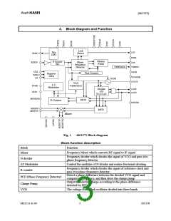
Fig. 1 AK1572 Block diagram
Block function description
Block
Mixer
Function
Frequency Mixer which converts RF signal to IF signal
Frequency divider which divides the signal of VCO and pass it to
phase frequency detector
N divider
Control the modulus of N divider and realize fractional dividing
ΔΣ Modulator
R counter
Frequency divider which divides the signal of reference clock and
pass it to phase frequency detector
Detect a phase difference between the divided VCO signal and
comparison frequency, and then drive the charge pump
Output the electric charge according to the phase difference
detected by PFD
PFD (Phase Frequency Detector)
Charge Pump
VCO
The voltage controlled oscillator divided into three bands
MS1551-E-00
3
2013//8

 AKM [ ASAHI KASEI MICROSYSTEMS ]