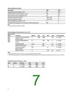
Absolute Maximum Ratings
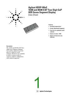
Description
HER
Units
mW
mA
mA
˚C
Average Power per Segment or DP
Peak Forward Current per Segment or DP
DC Forward Current per Segment or DP
Operating Temperature Range
65
100
25
–40 to +105
Storage Temperature Range
–40 to +105
˚C
Reverse Voltage per Segment or DP
Wavesoldering Temperature for 3 seconds 1.59 mm below body
5
V
250
˚C
Note:
1. Derate above 40˚C at 0.33 mA/˚C for HER.
Electrical/Optical Characteristics at T = 25˚C
A
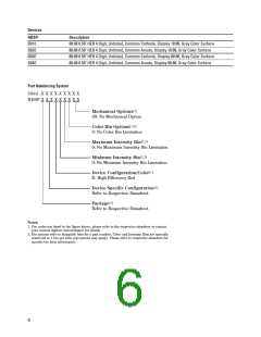
Device Series
HDSP-
Parameter
Symbol
Min.
Typ.
Max.
Units
Test Conditions
B01E
B02E
B03E
B04E
Luminous Intensity/Segment
(Digit Average)
I
3200
5500
µcd
I = 10 mA
F
V
Forward Voltage/Segment
or DP
V
2.05
2.60
V
I = 20 mA
F
F
Peak Wavelength
λ
λ
632
622
nm
nm
I = 20 mA
F
PEAK
d
Dominant Wavelength
I = 20 mA
F
Luminous Intensity
Matching Ratio
I
2:1
I = 10 mA
F
V-M
Reverse Current
I
100
µA
V = 5 V
R
R
Notes:
1. Typical specification for reference only. Do not exceed absolute maximum ratings.
2. The dominant wavelength, λ , is derived from the CIE chromaticity diagram and is that single wavelength which defines the color of the device.
d
Intensity Bin Limits (Tolerance 10%)
Rank
L
Symbol
Condition
I = 10 mA
Min.
3200
5050
Max.
5050
8000
Unit
µcd
µcd
I
I
V
V
F
M
I = 10 mA
F
7

 AGILENT [ AGILENT TECHNOLOGIES, LTD. ]