Agilent HCPL-7710, HCPL-0710
40 ns Propagation Delay,
CMOS Optocoupler
Data Sheet
Features
• +5 V CMOS compatibility
• 8 ns maximum pulse width
distortion
• 20 ns maximum prop. delay skew
• High speed: 12 Mbd
• 40 ns maximum prop. delay
Description
Basic building blocks of the
HCPL-x710 are a CMOS LED
driver IC, a high speed LED and a
CMOS detector IC. A CMOS logic
input signal controls the LED
driver IC which supplies current
to the LED. The detector IC
incorporates an integrated
photodiode, a high-speed
• 10 kV/ µs minimum common mode
rejection
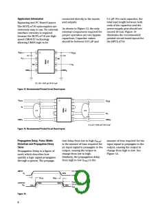
Available in either an 8-pin DIP or
SO-8 package style respectively,
the HCPL-7710 or HCPL-0710
optocouplers utilize the latest
CMOS IC technology to achieve
outstanding performance with
very low power consumption. The
HCPL-x710 require only two
bypass capacitors for complete
CMOS compatibility.
• -40°C to 100°C temperature range
• Safety and regulatory approvals
UL Recognized
3750 V rms for 1 min. per
UL 1577
CSA Component Acceptance
Notice # 5
transimpedance amplifier, and a
voltage comparator with an
output driver.
IEC/ EN/ DIN EN 60747-5-2
– VIORM = 630 Vpeak for
HCPL-7710 Option 060
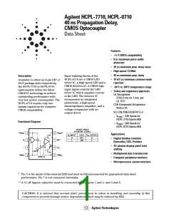
Functional Diagram
– VIORM = 560 Vpeak for
HCPL-0710 Option 060
TRUTH TABLE
(POSITIVE LOGIC)
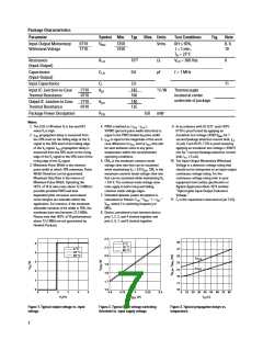
**V
1
2
8
7
V
**
DD2
DD1
Applications
V , INPUT
I
LED1
V
, OUTPUT
O
H
L
OFF
ON
H
L
• Digital fieldbus isolation:
DeviceNet, SDS, Profibus
V
I
NC*
I
O
• AC plasma display panel level
shifting
3
4
6
5
*
V
O
LED1
• Multiplexed data transmission
• Computer peripheral interface
• Microprocessor system interface
GND
GND
2
1
SHIELD
* Pin 3 is the anode of the internal LED and must be left unconnected for guaranteed data sheet
performance. Pin 7 is not connected internally.
** A 0.1 µF bypass capacitor must be connected between pins 1 and 4, and 5 and 8.
CAUTION: It is advised that normal static precautions be taken in handling and assembly of this
component to prevent damage and/or degradation which may be induced by ESD.

 AGILENT [ AGILENT TECHNOLOGIES, LTD. ]