Data Sheet
January 2000
1340-Type Lightwave Receiver
Pin Information
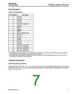
Table 1. Pin Descriptions
Pin Number
Description
1
2
Ground
Ground
3
Ground
4
Ground
5
No User Connection*
Ground
6
7
DATA
8
Ground
9
DATA
10
11
12
13
14
15
16
17
18
19
20
NIC or Optional VPIN
Vcc (5 V)
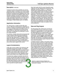
†
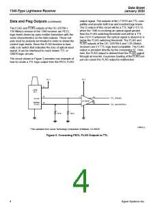
FLAG
Ground
FLAG
Ground
Ground
No User Connection*
No User Connection*
No User Connection*
No User Connection*
* Pins designated as no user connection are not connected internally within the receiver. However, to allow for future functional upgrades, it is
recommended that the user not make any connections to these pin positions.
† The link-status flag is a logic output that indicates the presence or absence of a minimum acceptable level of optical input. A logic high on
FLAG indicates the presence of a valid optical signal.
Handling Precautions
Mounting and Connections
The pigtail consists of a 39 in. ± 4 in. (1 m ± 10 cm), 62.5 µm core/125 µm cladding multimode fiber. The standard
fiber has a 0.036 in. (914 µm) diameter tight-buffered outer jacket. The minimum fiber bending radius during opera-
tion is 1.0 in. (25.4 mm).
Agere Systems Inc.
7

 AGERE [ AGERE SYSTEMS ]