ADV7180
SRLS, Select Raw Lock Signal, Address 0x51 [6]
COL[2:0], Count Out of Lock, Address 0x51 [5:3]
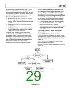
Using the SRLS bit, the user can choose between two sources for
determining the lock status (per Bits[1:0] in the Status Register 1).
Refer to Figure 16.
COL[2:0] determines the number of consecutive lines for which
the out-of-lock condition must be true before the system switches
into the unlocked state and reports this via Status 0 [1:0]. It counts
the value in lines of video.
•
The TIME_WIN signal is based on a line-to-line evaluation
of the horizontal synchronization pulse of the incoming
video. It reacts quite quickly.
Table 22. COL Function
COL[2:0]
Number of Video Lines
•
The FREE_RUN signal evaluates the properties of the
incoming video over several fields, taking vertical
synchronization information into account.
000
001
010
1
2
5
011
100 (default)
101
110
111
10
Setting SRLS to 0 (default) selects the FREE_RUN signal.
Setting SRLS to 1 selects the TIME_WIN signal.
FSCLE, FSC Lock Enable, Address 0x51 [7]
100
500
1000
100,000
The FSCLE bit allows the user to choose whether the status of
the color subcarrier loop is taken into account when the overall
lock status is determined and presented via Bits[1:0] in Status
Register 1. This bit must be set to 0 when operating the
ADV7180 in YPrPb component mode in order to generate a
reliable HLOCK status bit.
COLOR CONTROLS
These registers allow the user to control picture appearance,
including control of the active data in the event of video being
lost. These controls are independent of any other controls. For
instance, brightness control is independent from picture clamping,
although both controls affect the dc level of the signal.
When FSCLE is set to 0 (default), only the overall lock status is
dependent on horizontal sync lock.
CON[7:0], Contrast Adjust, Address 0x08 [7:0]
When FSCLE is set to 1, the overall lock status is dependent on
horizontal sync lock and FSC lock.
This register allows the user to control contrast adjustment of
the picture.
CIL[2:0], Count Into Lock, Address 0x51 [2:0]
Table 23. CON Function
CIL[2:0] determines the number of consecutive lines for which
the into lock condition must be true before the system switches
into the locked state and reports this via Status 0 [1:0]. The bit
counts the value in lines of video.
CON[7:0]
0x80 (default)
0x00
Description
Gain on luma channel = 1
Gain on luma channel = 0
Gain on luma channel = 2
0xFF
Table 21. CIL Function
SD_SAT_Cb[7:0], SD Saturation Cb Channel,
Address 0xE3 [7:0]
CIL[2:0]
Number of Video Lines
000
1
001
010
011
100 (default)
101
2
5
10
100
500
1000
100,000
This register allows the user to control the gain of the Cb
channel only, which in turn adjusts the saturation of the picture.
Table 24. SD_SAT_Cb Function
SD_SAT_Cb[7:0] Description
0x80 (default)
0x00
0xFF
Gain on Cb channel = 0 dB
Gain on Cb channel = −42 dB
Gain on Cb channel = +6 dB
110
111
Rev. A | Page 25 of 112

 ADI [ ADI ]