ADIS16362
Status
DIAGNOSTICS
The error flags provide indicator functions for common
system level issues. All of the flags are cleared (set to 0) after
each DIAG_STAT register read cycle. If an error condition
remains, the error flag returns to 1 during the next sample
cycle. The DIAG_STAT[1:0] bits do not require a read of this
register to return to 0. If the power supply voltage goes back
into range, these two flags are cleared automatically.
Self-Test
The self-test function allows the user to verify the mechanical
integrity of each MEMS sensor. It applies an electrostatic force to
each sensor element, which results in mechanical displacement
that simulates a response to actual motion. Table 1 lists the
expected response for each sensor, which provides pass/fail
criteria. Set MSC_CTRL[10] = 1 (DIN = 0xB504) to run the
internal self-test routine, which exercises all inertial sensors,
measures each response, makes pass/fail decisions, and reports
them to error flags in the DIAG_STAT register. MSC_CTRL[10]
resets itself to 0 after completing the routine. The MSC_CTRL[9:8]
bits provide manual control over the self-test function for inves-
tigation of potential failures. Table 25 outlines an example test
flow for using this option to verify the x-axis gyroscope function.
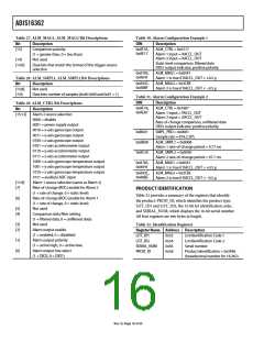
Table 26. DIAG_STAT Bit Descriptions
Bit
[±ꢀ]
[±4]
[±3]
[±2]
[±±]
[±0]
[9]
Description
Z-axis accelerometer self-test failure (± = fail, 0 = pass)
Y-axis accelerometer self-test failure (± = fail, 0 = pass)
X-axis accelerometer self-test failure (± = fail, 0 = pass)
Z-axis gyroscope self-test failure (± = fail, 0 = pass)
Y-axis gyroscope self-test failure (± = fail, 0 = pass)
X-axis gyroscope self-test failure (± = fail, 0 = pass)
Alarm 2 status (± = active, 0 = inactive)
Alarm ± status (± = active, 0 = inactive)
Not used
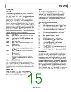
Table 25. Manual Self-Test Example Sequence
DIN
Description
[8]
[ꢁ]
0xBꢃ0±
0xB904
0xB802
SMPL_PRD[ꢁ:0] = 0x0±, sample rate = 8±9.2 SPS
SENS_AVG[±ꢀ:8] = 0x04, gyro range = ±300°/sec
SENS_AVG[ꢁ:0] = 0x02, four-tap averaging filter
Delay = ꢀ0 ms
Read XGYRO_OUT
MSC_CTRL[9] = ±, gyroscope negative self-test
Delay = ꢀ0 ms
[ꢃ]
[ꢀ]
[4]
Flash test, checksum flag (± = fail, 0 = pass)
Self-test diagnostic error flag (± = fail, 0 = pass)
Sensor overrange (± = fail, 0 = pass)
0x0400
0xBꢀ02
[3]
[2]
SPI communication failure (± = fail, 0 = pass)
Flash update failure (± = fail, 0 = pass)
[±]
Power supply above ꢀ.2ꢀ V
0x0400
Read XGYRO_OUT
(± = power supply ≥ ꢀ.2ꢀ V, 0 = power supply ≤ ꢀ.2ꢀ V)
Determine whether the bias in the gyroscope
output changes according to the expectation set
in Table ±
[0]
Power supply below 4.ꢁꢀ V
(± = power supply ≤ 4.ꢁꢀ V, 0 = power supply ≥ 4.ꢁꢀ V)
0xBꢀ0±
0x0400
MSC_CTRL[9:8] = 0±, gyroscope/accelerometer
positive self-test
Delay = ꢀ0 ms
Alarm Registers
The alarm function provides monitoring for two independent
conditions. The ALM_CTRL register provides control inputs
for data source, data filtering (prior to comparison), static
comparison, dynamic rate-of-change comparison, and output
indicator configurations. The ALM_MAGx registers establish
the trigger threshold and polarity configurations. Table 30 gives
an example of how to configure a static alarm. The ALM_SMPLx
registers provide the numbers of samples to use in the dynamic
rate-of-change configuration. The period equals the number in
the ALM_SMPLx register multiplied by the sample period time,
which is established by the SMPL_PRD register. See Table 31 for
an example of how to configure the sensor for this type of function.
Read XGYRO_OUT
Determine whether the bias in the gyroscope
changed according to the self-test response in
Table ±
0xBꢀ00
MSC_CTRL[±ꢀ:8] = 0x00
Zero motion provides results that are more reliable. The set-
tings in Table 25 are flexible and allow for optimization around
speed and noise influence. For example, using fewer filtering
taps decreases delay times but increases the possibility of noise
influence.
Memory Test
Setting MSC_CTRL[11] = 1 (DIN = 0xB508) performs a
checksum verification of the flash memory locations. The
pass/fail result is loaded into DIAG_STAT[6].
Rev. 0 | Page ±ꢀ of 20

 ADI [ ADI ]