ADIS16362
Digital Filtering
Internal Sample Rate
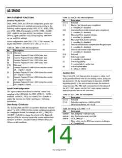
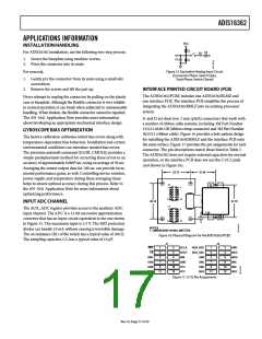
A programmable low-pass filter can provide additional noise
reduction on the inertial sensor outputs. This filter contains two
cascaded averaging filters that provide a Bartlett window, FIR filter
response (see Figure 14). For example, set SENS_AVG[2:0] = 100
(DIN = 0xB804) to set each stage to 16 taps. When used with the
default sample rate of 819.2 SPS, this value reduces the sensor
bandwidth to approximately 16 Hz.
The SMPL_PRD register provides discrete sample rate settings
using the bit assignments in Table 18 and the following equation:
tS = tB × (NS + 1)
For example, when SMPL_PRD[7:0] = 0x0A, the sample rate is
149 SPS.
Table 18. SMPL_PRD Bit Descriptions
0
Bit
Description (Default = 0x0001)
[±ꢀ:8]
[ꢁ]
Not used
Time base (tB)
0 = 0.ꢃ±03ꢀ ms, ± = ±8.92± ms
Increment setting (NS)
Internal sample period = tS = tB × (NS + ±)
–20
–40
–60
–80
[ꢃ:0]
The default sample rate setting of 819.2 SPS preserves the sensor
bandwidth and provides optimal performance. For systems that
value slower sample rates, keep the internal sample rate at
819.2 SPS. Use the programmable filter (SENS_AVG) to reduce
the bandwidth, which helps to prevent aliasing. The data ready
function (MSC_CTRL) can drive an interrupt routine that uses
a counter to help ensure data coherence at the reduced rates.
–100
N = 2
N = 4
N = 16
N = 64
–120
–140
0.001
0.01
0.1
1
FREQUENCY (Ratio)
Figure 14. Bartlett Window, FIR Filter Frequency Response
(Phase Delay = N Samples)
Power Management
Setting SMPL_PRD ≥ 0x0A also sets the sensor to low power
mode. For systems that require lower power dissipation, in-
system characterization helps users to quantify the associated
performance trade-offs. In addition to sensor performance, this
mode affects SPI data rates (see Table 2). Set SLP_CNT[8] = 1
(DIN = 0xBB01) to start the indefinite sleep mode, which
Dynamic Range
The SENS_AVG[10:8] bits provide three dynamic range settings
for this gyroscope. The lower dynamic range settings ( 75°/sec
and 150°/sec) limit the minimum filter tap sizes to maintain
resolution. For example, set SENS_AVG[10:8] = 010 (DIN =
0xB902) for a measurement range of 150°/sec. Because this
setting can influence the filter settings, program SENS_AVG[10:8]
and then SENS_AVG[2:0] if more filtering is required.
CS
requires a
assertion (high to low), reset, or power cycle to
wake up. Use SLP_CNT[7:0] to put the device into sleep mode
for a specified period. For example, SLP_CNT[7:0] = 0x64
(DIN = 0xBA64) puts the ADIS16362 to sleep for 50 sec.
Table 20. SENS_AVG Bit Descriptions
Bit
Description
Table 19. SLP_CNT Bit Descriptions
[±ꢀ:±±]
[±0:8]
Not used
Bit
Description
Measurement range (sensitivity) selection
±00 = ±300°/sec (default condition)
0±0 = ±±ꢀ0°/sec, filter taps ≥ 4 (Bits[2:0] ≥ 0x02)
00± = ±ꢁꢀ°/sec, filter taps ≥ ±ꢃ (Bits[2:0] ≥ 0x04)
Not used
[±ꢀ:9]
[8]
[ꢁ:0]
Not used
Indefinite sleep mode; set to ±
Programmable sleep time bits, 0.ꢀ sec/LSB
[ꢁ:3]
[2:0]
Number of taps in each stage, N = 2M
Rev. 0 | Page ±3 of 20

 ADI [ ADI ]