ADIS16362
Restoring Factory Calibration
CALIBRATION
Set GLOB_CMD[1] = 1 (DIN = 0xBE02) to execute the factory
calibration restore function. This function resets each user cali-
bration register to 0x0000 (see Table 15 and Table 16), resets all
sensor data to 0, and automatically updates the flash memory
within 50 ms (see Table 17).
Manual Bias Calibration
The bias offset registers in Table 15 and Table 16 provide a
manual adjustment function for the output of each sensor. For
example, if XGYRO_OFF = 0x1FF6 (DIN = 0x9B1F, 0x9AF6),
the XGYRO_OUT offset shifts by −10 LSBs, or −0.125°/sec.
Linear Acceleration Bias Compensation (Gyroscope)
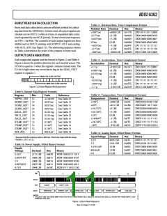
Table 15. XGYRO_OFF, YGYRO_OFF, ZGYRO_OFF
Bit Descriptions
Set MSC_CTRL[7] = 1 (DIN = 0xB486) to enable correction for
low frequency acceleration influences on gyroscope bias. Note
that the DIN sequence also preserves the factory default condi-
tion for the data ready function (see Table 22).
Bit
Description (Default = 0x0000)
[±ꢀ:±3]
[±2:0]
Not used.
Data bits. Twos complement, 0.0±2ꢀ°/sec per LSB.
Typical adjustment range = ±ꢀ0°/sec.
OPERATIONAL CONTROL
Global Commands
Table 16. XACCL_OFF, YACCL_OFF, ZACCL_OFF
Bit Descriptions
The GLOB_CMD register provides trigger bits for several use-
ful functions. Setting the assigned bit to 1 starts each operation,
which returns the bit to 0 after completion. For example, set
GLOB_CMD[7] = 1 (DIN = 0xBE80) to execute a software
reset, which stops the sensor operation and runs the device
through its start-up sequence. This sequence includes loading
the control registers with their respective flash memory locations
prior to producing new data. Reading the GLOB_CMD register
(DIN = 0x3E00) starts the burst read sequence.
Bit
Description (Default = 0x0000)
[±ꢀ:±2]
[±±:0]
Not used.
Data bits. Twos complement, 0.333 mg/LSB.
Typical adjustment range = ±0.3 g.
Gyroscope Automatic Bias Null Calibration
Set GLOB_CMD[0] = 1 (DIN = 0xBE01) to execute the auto-
matic bias null calibration function. This function measures all
three gyroscope output registers and then loads each gyroscope
offset register with the opposite value to provide a quick bias
calibration. All sensor data is then reset to 0, and the flash
memory is updated automatically within 50 ms (see Table 17).
Table 17. GLOB_CMD Bit Descriptions
Bit
Description
[±ꢀ:8] Not used
[ꢁ]
[ꢃ:ꢀ]
[4]
[3]
[2]
[±]
[0]
Software reset command
Not used
Gyroscope Precision Automatic Bias Null Calibration
Set GLOB_CMD[4] = 1 (DIN = 0xBE10) to execute the precision
automatic bias null calibration function. This function takes the
sensor offline for 30 sec while it collects a set of data and calculates
more accurate bias correction factors for each gyroscope. After
this function is executed, the newly calculated correction factor
is loaded into the gyroscope offset registers, all sensor data is
reset to 0, and the flash memory is updated automatically within
50 ms (see Table 17).
Precision autonull command
Flash update command
Auxiliary DAC data latch
Factory calibration restore command
Autonull command
Rev. 0 | Page ±2 of 20

 ADI [ ADI ]