AD843
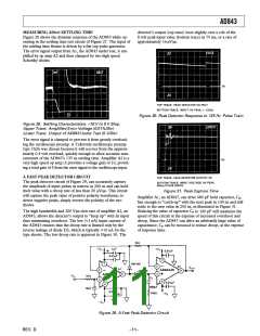
MEASURING AD843 SETTLING TIME
detector’s output (top trace) loses slightly over a volt of the
8 volt peak input value (bottom trace) in 75 ms, or a rate of
approximately 16 µV/µs.
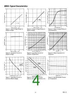
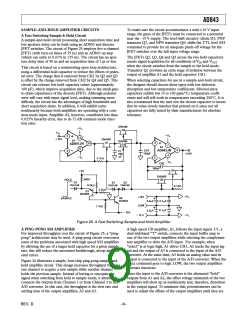
Figure 28 shows the dynamic response of the AD843 while op-
erating in the settling time test circuit of Figure 27. The input of
the settling time fixture is driven by a flat-top pulse generator.
The error signal output from A1, the AD843 under test, is am-
plified by op amp A2 and then clamped by two high speed
Schottky diodes.
Figure 30. Peak Detector Response to 125 Hz Pulse Train
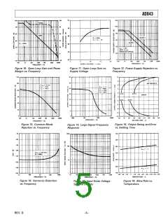
Figure 28. Settling Characteristics: +10 V to 0 V Step.
Upper Trace: Amplified Error Voltage (0.01%/Div)
Lower Trace: Output of AD843 Under Test (5 V/Div)
The error signal is clamped to prevent it from greatly overload-
ing the oscilloscope preamp. A Tektronix oscilloscope preamp
type 7A26 was chosen because it will recover from the approxi-
mately 0.4 volt overload, quickly enough to allow accurate mea-
surement of the AD843’s 135 ns settling time. Amplifier A2 is a
very high speed op amp; it provides a voltage gain of 10, provid-
ing a total gain of 5 from the error signal to the oscilloscope input.
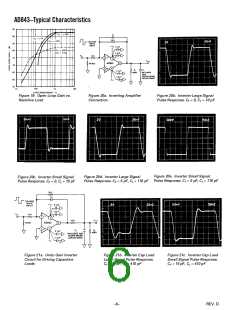
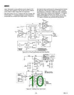
A FAST PEAK DETECTOR CIRCUIT
The peak detector circuit of Figure 29, can accurately capture
the amplitude of input pulses as narrow as 200 ns and can hold
their value with a droop rate of less than 20 µV/µs. This circuit
will capture the peak value of positive polarity waveforms; to
detect negative peaks, simply reverse the polarity of the two
diodes.
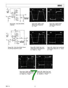
Figure 31. Peak Capture Time
Amplifier A1, an AD847, can drive 680 pF hold capacitor, CP,
fast enough to “catch-up” with the next peak in 100 ns and still
settle to the new value in 250 ns, as illustrated in Figure 31.
Reducing the value of capacitor CP to 100 pF will maximize the
speed of this circuit at the expense of increased overshoot and
droop. Since the AD847 can drive an arbitrarily large value of
capacitance, CP can be increased to reduce droop, at the expense
of response time.
The high bandwidth and 200 V/µs slew rate of amplifier A2, an
AD843, allows the detector’s output to “keep up” with its input
thus minimizing overshoot. The low (<1 nA) input current of
the AD843 ensures that the droop rate is limited only by the
reverse leakage of diode D2, which is typically <10 nA for the
type shown. The low droop rate is apparent in Figure 30. The
Figure 29. A Fast Peak Detector Circuit
REV. D
–11–

 ADI [ ADI ]