AD8240
USING/EVALUATING THE AD8240 LED DRIVER MONITOR
Shunt Resistor Selection
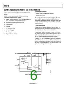
Figure 3 shows a connection diagram for a typical application.
The shunt resistor is chosen by the equation
SETUP
RSHUNT ≤ 0.2V ILOAD
In order to set up and evaluate the AD8240, the following
components and equipment are needed:
For example if the load is expected to be 500 mA, the shunt
value should be equal to or less than 0.4 Ω. This keeps the
output of the current sense amplifier from being greater than
4.8 V in normal operation to prevent noise from causing the
output to latch off.
•
A shunt resistor (typically 0.1 Ω to 0.5 Ω depending on the
load). See the Shunt Resistor Selection section.
•
•
•
•
•
•
•
A transistor (the type depends on the load)
Two capacitors
Circuit Configuration
LED load
Connect the pass transistor, capacitors, and LED load(s) as
shown in Figure 3. It is important to note that the value of CM
should be at least 22 nF to ensure circuit stability.
5 V reference voltage
9 V to 27 V supply
Oscilloscope
The LED lamp should be configured to expect 12 V. This is
the result of selecting the series/parallel combinations of LEDs
and series resistors. The series resistors can be used to adjust
for LED supplier brightness variations from lot to lot.
Digital voltmeter (DVM)
Connect 5 V to Pin 2 (5 V reference) and at least 9 V to Pin 5
(VPLUS). It may be necessary to raise the VPLUS voltage to more
than 13 V, depending on the drop across the pass transistor, for
the output to be regulated at 12 V. This varies according to the
application and the pass transistor type.
.
R
SHUNT
V
BATT
C
M
CL
47nF
V
V
22nF
PLUS
SHUNT
O
BASE
5
6
8
7
R
SENSE
V
1
SENSE
10kΩ
5V
2
3
REFERENCE
R1
350kΩ
LATCH-OFF
DRIVER
PWM
R2
250kΩ
4
GND
Figure 3. Connections for Typical Applications
Rev. 0 | Page 6 of 12

 ADI [ ADI ]