AD652
These resistors should be selected such that the following equa-
tion holds:
2 RF
RG
10V = VBRIDGE
+1
where 10 kΩ ≤ RF ≤ 20 kΩ, and VBRIDGE is the maximum
output voltage of the bridge.
The bridge output may be unipolar, as is the case for most
pressure transducers, or it may be bipolar as in some strain mea-
surements. If the signal is unipolar, the reference input of the
AD625 (Pin 7) is simply grounded. If the bridge has a bipolar
output, however, the AD652 reference can be tied to Pin 7,
thereby, converting a 5 volt signal (after gain) into a 0 volt to
+10 volt input for the SVFC.
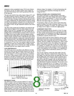
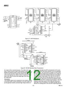
Figure 30. Delta Modulator lnput Signal and Ramp-Wise
Approximation
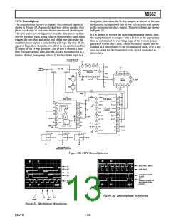
Figure 31. Delta Modulator Input Signal, Ramp-Wise
Approximation and Output Frequency
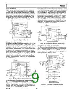
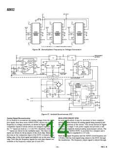
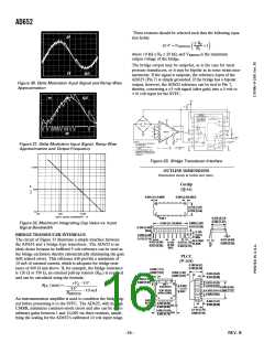
Figure 33. Bridge Transducer Interface
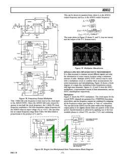
OUTLINE DIMENSIONS
Dimensions shown in inches and (mm).
Cerdip
(Q-16)
0.005 (0.13) MIN
16
0.080 (2.03) MAX
9
0.310 (7.87)
0.220 (5.59)
1
8
0.320 (8.13)
0.290 (7.37)
PIN 1
0.840 (21.34) MAX
0.060 (1.52)
0.015 (0.38)
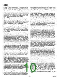
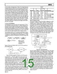
Figure 32. Maximum Integrating Cap Value vs. Input
Signal Bandwidth
0.200 (5.08)
MAX
0.150
(3.81)
MIN
SEATING
PLANE
0.200 (5.08)
0.125 (3.18)
BRIDGE TRANSDUCER INTERFACE
0.015 (0.38)
The circuit of Figure 33 illustrates a simple interface between
the AD652 and a bridge-type transducer. The AD652 is an
ideal choice because its buffered 5 volt reference can be used as
the bridge excitation thereby ratiometrically eliminating the gain
drift related errors. This reference will provide a minimum of
10 mA of external current, which is adequate for bridge resis-
tance of 600 Ω and above. If, for example, the bridge resistance
is 120 Ω or 350 Ω, an external pull-up resistor (RPU) is required
and can be calculated using the formula:
0.023 (0.58)
0.014 (0.36)
0.100
(2.54)
BSC
0.070 (1.78)
0.030 (0.76)
15°
0°
0.008 (0.20)
PLCC
(P-20A)
0.180 (4.57)
0.165 (4.19)
0.048 (1.21)
0.042 (1.07)
0.056 (1.42)
0.042 (1.07)
0.025 (0.63)
0.015 (0.38)
0.048 (1.21)
0.042 (1.07)
3
19
0.021 (0.53)
0.013 (0.33)
+VS – 5V
4
8
18
PIN 1
RPU (max) =
0.050
(1.27)
BSC
IDENTIFIER
0.330 (8.38)
0.290 (7.37)
5V
TOP VIEW
(PINS DOWN)
–10 mA
0.032 (0.81)
0.026 (0.66)
RBRIDGE
14
13
9
An instrumentation amplifier is used to condition the bridge sig-
nal before presenting it to the SVFC. The AD625, with its high
CMRR, minimizes common-mode errors and also can be set to
arbitrary gains between 1 and 10,000 via three resistors, simpli-
fying the scaling for the AD652’s calibrated 10 volt input range.
0.020
(0.50)
R
0.040 (1.01)
0.025 (0.64)
0.356 (9.04)
0.350 (8.89)
SQ
0.110 (2.79)
0.085 (2.16)
0.395 (10.02)
0.385 (9.78)
SQ
–16–
REV. B

 ADI [ ADI ]