TP2111/TP2111N/TP2112/TP2114
Nanopower 300nA, 1.8V, Rail-to-Rail Input/Output Op-amps
are of equal length so that thermal conduction is in equilibrium. Keep heat sources on the PCB as far away from
amplifier input circuitry as is practical.
The use of a ground plane is highly recommended. A ground plane reduces EMI noise and also helps to maintain a
constant temperature across the circuit board.
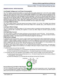
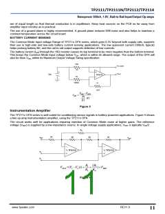
BATTERY CURRENT SENSING
The Common Mode Input voltage Range of TP211x OPA series, which goes 0.3V beyond both supply rails, supports
their use in high-side and low-side battery current sensing applications. The low quiescent current (300nA, typical)
helps prolong battery life, and the rail-to-rail output supports detection of low currents.
The battery current (IDD) through the 10Ω resistor causes its top terminal to be more negative than the bottom terminal.
This keeps the Common Mode Input voltage below VDD, which is within its allowed range. The output of the OPA will
also be blow VDD, within its Maximum Output Voltage Swing specification.
10Ω
To Load
R3
VOUT
DC
TP2111
R2
100kΩ
R1
1MΩ
VDD VOUT
IDD
R1
R3
R2
Figure 3
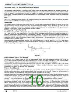
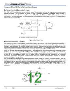
Instrumentation Amplifier
The TP211x OPA series is well suited for conditioning sensor signals in battery-powered applications. Figure 4 shows
a two op-amp instrumentation amplifier, using the TP211x OPA.
The circuit works well for applications requiring rejection of Common Mode noise at higher gains. The reference
voltage (VREF) is supplied by a low-impedance source. In single voltage supply applications, VREF is typically VDD/2.
RG
R1
R2
R2
R1
VREF
VOUT
½ TP2112
½ TP2112
V1
V2
R
2R
1 ) VREF
R2 RG
1
VOUT =(V V2 )(1
1
Figure 4
www.3peakic.com
REV1.0
11

 3PEAK [ 3PEAK ]